Apparatus for molding optical element

a technology of optical elements and molding apparatus, which is applied in the direction of glass pressing apparatus, glass making apparatus, manufacturing tools, etc., can solve the problems of inability to convey molds, deterioration of molding accuracy, and gap between the tables, so as to prevent thermal influence, smooth conveying, and smooth conveying

Inactive Publication Date: 2008-09-04
ASAHI GLASS CO LTD
View PDF0 Cites 3 Cited by
  • Summary
  • Abstract
  • Description
  • Claims
  • Application Information

AI Technical Summary

Benefits of technology

[0034]According to the invention of Claim 1, by providing a gap of at least about a half of the length of a mold in the conveying direction between tables of different process steps, sufficient heat insulation effect is obtained by the gap, and it is possible to prevent adjacent tables from providing thermal influence to each other. Accordingly, temperature slope is not formed in a mold, and uniform temperature distribution is maintained in each table, whereby a high-precision press-molded product is obtained. In this construction, a mold is conveyed without using a conventional method of sliding the mold, and the mold is conveyed as its weight is supported by a tool other than the tables, whereby the mold can be smoothly conveyed over a gap between tables without being dropped into the gap.
[0035]According to the invention of Claim 2, by conveying a mold as it is lifted up, the mold can be smoothly conveyed even if there is a large gap between tables of different process steps, or even if there is a height difference in a vertical direction between surfaces of the tables. Accordingly, it becomes possible to provide a gap for heat insulation between tables of different process steps, or to dispose e.g. a heat-insulation partition member, whereby it is possible to prevent thermal influence between process steps to obtain a high precision molded product.
[0036]Further, by conveying the mold as it is lifted up from a table, surfaces of the mold and the table become to be scarcely worn, whereby there is no need of employing expensive abrasion resistance materials, and there is less need of replacing the mold or the table due to wearing, and production cost can be reduced.
[0037]According to the invention of Claim 3, since the conveying jig supports a mold with a predetermined gap in a horizontal direction, the conveying jig does not apply a shock in the horizontal direction to the mold. Accordingly, a molding material for an optical element does not shift in the mold, and molding precision is not deteriorated. Further, even if there is a variation of outer dimensions of molds, the conveying jig can securely support the molds and convey the molds. Moreover, since the molds are lifted up by the conveying jig, even if e.g. the number, the arrangement or the dimension of molds to be set in the conveying jig, is changed, it is only necessary to replace the conveying jig, and the conveying mechanism can be continuously used. Accordingly, there is no need of redesigning and rebuilding of the conveying mechanism, and thus, the conveying mechanism is excellent in general-purpose use capability.
[0038]According to the invention of Claim 4, since the gap in a horizontal direction between the conveying jig and a mold, is larger than thermal expansion amount of the mold, even if expansion or shrinkage occurs by heating or cooling of the mold, it is possible to smoothly convey the mold without being affected by the dimension change.
[0039]According to the invention of Claim 5, since a gap in a horizontal direction between the conveying jig and a mold, is larger than variation of external dimension of the mold, even if there occurs an external dimension error, it is possible to smoothly convey the mold without being affected by the dimension error of each mold. Accordingly, it is possible to reduce a work load for controlling external dimensions of molds, and to reduce the cost.

Problems solved by technology

However, it is not possible to convey the molds by sliding the molds if there is a large gap or a height difference between the tables.
If the tables are closely arranged to each other to cope with this problem, each table becomes susceptible to thermal influence of adjacent process steps, and there occurs a problem that molding accuracy is deteriorated.
However, there is a case where a gap is required between the tables by separating a conveying path, for e.g. thermal insulation between process step zones.
If the gap is larger, the mold inclines by its own weight, and thus, can not be conveyed to an adjacent table.
Accordingly, it is not possible to obtain sufficient effect of reducing thermal influence between the tables by the method of separating the tables from each other.
Further, by a friction at the time of sliding, the molds or the tables are worn in a short time, which deteriorates molding accuracy.
Accordingly, the molds or the tables are frequently replaced, which increases a cost.
If the position of the molding material is shifted, thickness of a molded lens becomes asymmetric and molding accuracy is deteriorated.
Furthermore, if the number of molds conveyed at the same time increases, operation stroke of the pole increases, which makes entire apparatus large sized and increases required rigidity of the pole to obtain accurate positioning.
Further, in a case where the conveying jig for positioning molds is always contacts the molds, both of the molds and the conveying jig become heated (or cooled) objects in the heating or the cooling step, which increases total heat capacity and requires unnecessary heating and cooling to consume unnecessary amount of heat.
In the case of such a mold having a body mold accommodating the top mold and the bottom mold, it is not possible to lift up the mold by supporting the body mold since the bottom mold falls down.
When the mold is lifted up to be conveyed, it becomes necessary to position the mold again after it is conveyed, which requires an apparatus for positioning the mold, which increases a cost and requires extra time to deteriorate productivity.
However, since the temperature of a mold before the molding step is lower than the temperature at the time of heating, there is a gap between a body mold and top and bottom molds in the mold before the molding step.
Accordingly, even if the position of outer periphery of the body mold is positioned, center positions of the top mold and the bottom mold are not always aligned, and thus, molding precision is not sufficient.

Method used


Image

  • Apparatus for molding optical element
  • Apparatus for molding optical element
  • Apparatus for molding optical element

Examples


Embodiment Construction

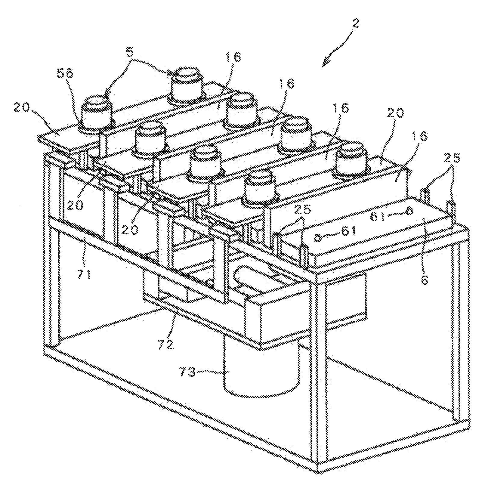
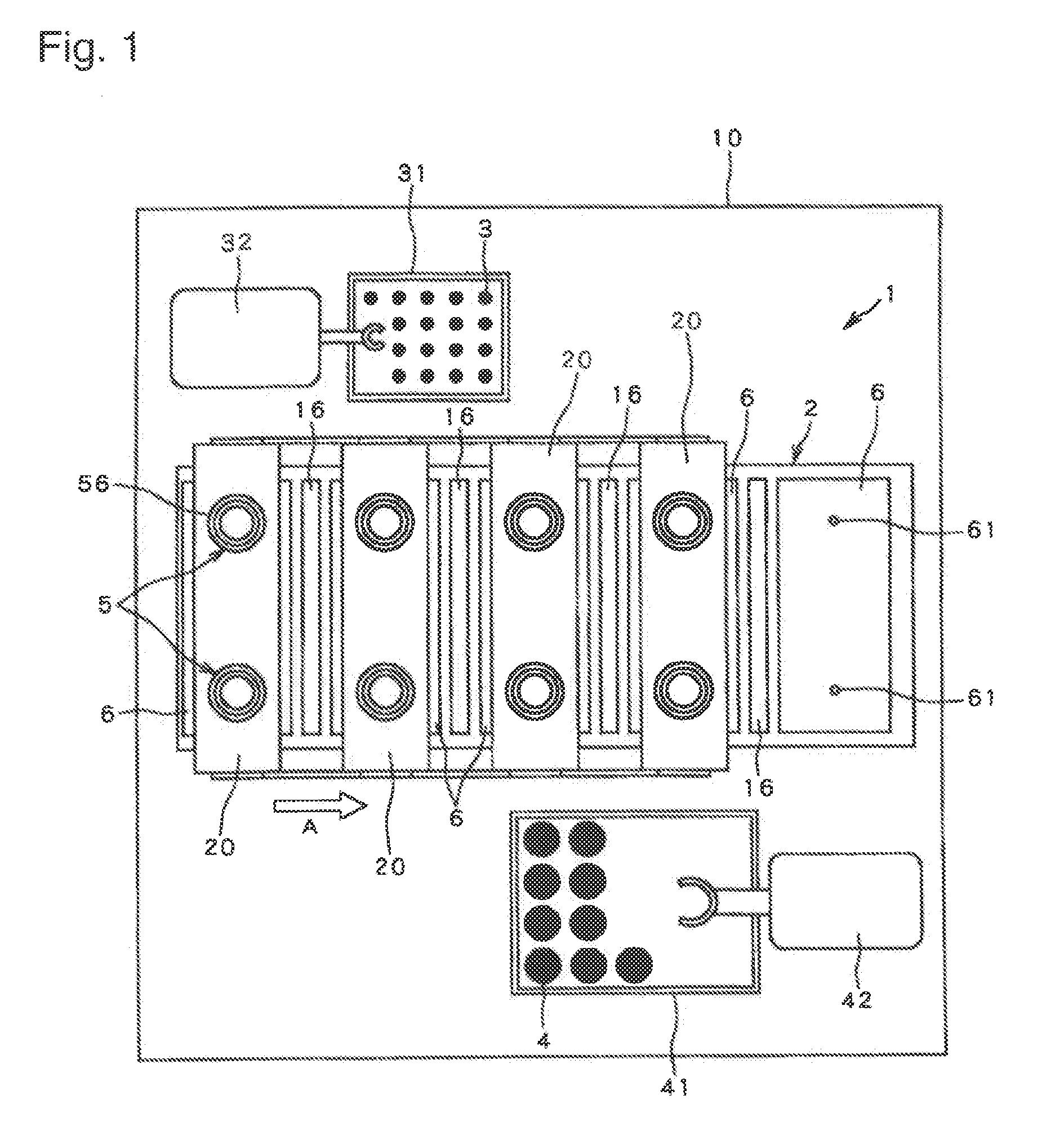
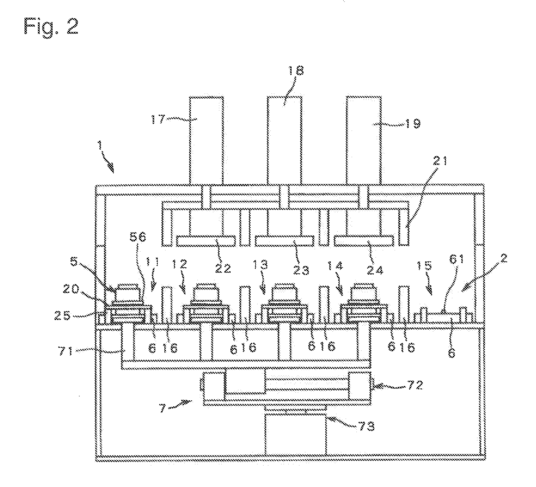
[0056]FIGS. 1 to 3 show an example of the present invention. FIG. 1 is a plan view, FIG. 2 is a front view and FIG. 3 is a perspective view.

[0057]FIG. 1 is a plan view of entire apparatus. A molding apparatus 1 is accommodated in an air-tight chamber 10, and the chamber 10 is filled with a non-oxidative atmosphere, for example, nitrogen atmosphere.

[0058]A conveying path 2 of linear shape is provided in the chamber 2 to convey a mold 5 in a direction of an arrow A from left to right in the figure. Adjacently to the conveying path 2, a molding material tray 31 for accommodating molding materials 3 being glass balls, and a product tray 41 in which press-molded products 4 being molded optical elements, are disposed, and in the vicinity of the trays 31 and 41, robots 32 and 42 are disposed to convey the molding materials 3 and the products 4 respectively. Replacement of the molding material tray 31 and the product tray 41 are carried out through an in-out port, not shown, of the chamber ...


PUM

PropertyMeasurementUnit
lengthaaaaaaaaaa
timeaaaaaaaaaa
shrinkageaaaaaaaaaa

Abstract

A molding apparatus for optical elements is provided, which reduces thermal influence receiving from adjacent production steps by a simple structure and simple process steps, and which can carry out molding of precision optical elements.The apparatus comprises a conveying path 2 having a plurality of tables 6 continuously arranged to circulate a mold 15 constituted by a top mold, a bottom mold and a body mold, and the apparatus applies heating, press-molding and cooling steps to the mold 5 placed on the tables 6 during the circulation, wherein a gap of at least about a half of the length of the mold in the conveying direction is provided between the tables for different process steps. The mold 5 is conveyed between the tables 6 as it is lifted up from the tables 6 at a time of conveying the mold 6.

Description

CROSS REFERENCE TO RELATED APPLICATIONS[0001]This application is a continuation application of PCT / JP06 / 317577, filed Sep. 5, 2006, which claims benefit of and priority to Japanese Patent Application No. 2005-257843 filed on Sep. 6, 2005, the entire contents of each of which are incorporated herein by reference.TECHNICAL FIELD[0002]The present invention relates to a molding apparatus for press-molding optical elements such as high-precision glass lenses to be used for optical instruments.BACKGROUND ART[0003]Heretofore, molding apparatuses have been used for producing a glass lens by press-molding a heated and softened glass molding material by pressurizing the material. Since these apparatuses can omit e.g. a polishing step, they are recently widely used as production apparatuses capable of performing mass production.[0004]Production method of glass lenses using such a production apparatus, is as follows. For example, a glass molding material preformed to have a ball shape is set in...

Claims


Application Information

Patent Timeline
Patent Type & Authority Applications(United States)
IPC IPC(8): C03B11/00C03B11/16
CPCC03B11/08C03B2215/86C03B2215/80C03B2215/72Y02P40/57C03B11/00C03B11/06
Inventor TANAKA, SHINJI
Owner ASAHI GLASS CO LTD
Why Eureka
Try Eureka