Metal Blank with Binder Trim Component and Method

a technology of metal blanks and components, applied in the field of metal blanks, can solve the problems of surface distortion, wrinkles and/or other surface distortions of formed parts, and tear or cracks in formed parts

Active Publication Date: 2008-09-04
TWB CO LLC
View PDF39 Cites 24 Cited by
  • Summary
  • Abstract
  • Description
  • Claims
  • Application Information

AI Technical Summary

Benefits of technology

[0006]According to another aspect, there is provided a metal blank that comprises an outer periphery, a binder trim component, and a part component. The binder trim component has a non-linear section that includes a projection, a recess, and a flat secti

Problems solved by technology

If too little material is drawn in, then it can result in tears or cracks in the formed part; conversely,

Method used


Image

  • Metal Blank with Binder Trim Component and Method
  • Metal Blank with Binder Trim Component and Method
  • Metal Blank with Binder Trim Component and Method

Examples


embodiment 300

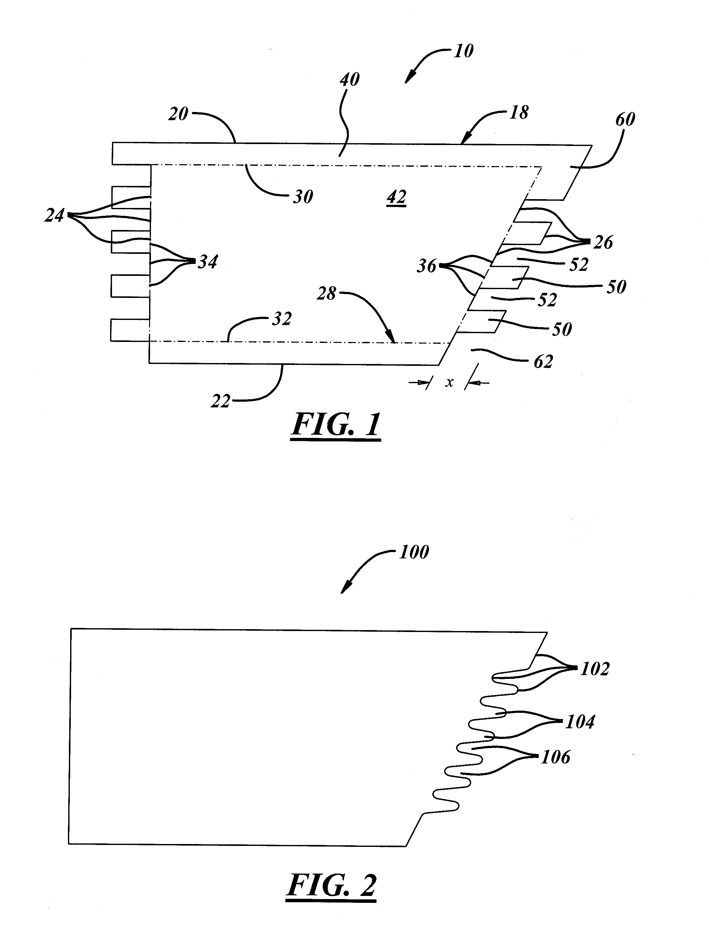
[0035]Turning now to FIG. 4, there is shown a flowchart demonstrating some of the primary steps of an embodiment 300 of a method for forming a three-dimensional metal structure. First, a sheet metal coil is received and processed by treating, washing and / or slitting the coil, wiping the coil of materials such as oil, and performing any other prerequisite processing steps known to those skilled in the art, step 302. Once the sheet metal coil has been properly processed, it is sent through a blanking operation, step 304, in which a plurality of metal blanks each having an outer periphery similar to the ones shown in FIGS. 1 and 2 are created. As previously explained, the binder components of adjoining metal blanks have corresponding projections and recesses that share material so that the total amount of material needed is reduced. According to one embodiment, each of the individual metal blanks are then laser or otherwise welded to a sheet metal piece of a different thickness or grad...

embodiment 400

[0037]In FIG. 5, there is shown an embodiment 400 of a method for designing a binder trim component for a metal blank, where the metal blank is used in a subsequent metal forming operation to make a proposed part. Beginning with step 402, the method performs a forming simulation that analyzes a metal forming operation on the proposed part. According to one embodiment, the forming simulation is a computer-based forming simulation that uses non-linear finite element analysis to simulate the metal forming operation and predict common defects such as splits, tears, wrinkles, puckers, springback, material thinning, and the like, as well as the draw-in distances of various sections. As previously mentioned, one suitable program for performing such a simulation is PAM-STAMP sold by ESI Group; however, other programs could certainly be used instead. According to another embodiment, the forming simulation is a physical-based forming simulation, such as a circle-grid analysis, that analyzes m...


PUM

PropertyMeasurementUnit
Lengthaaaaaaaaaa
Lengthaaaaaaaaaa
Lengthaaaaaaaaaa

Abstract

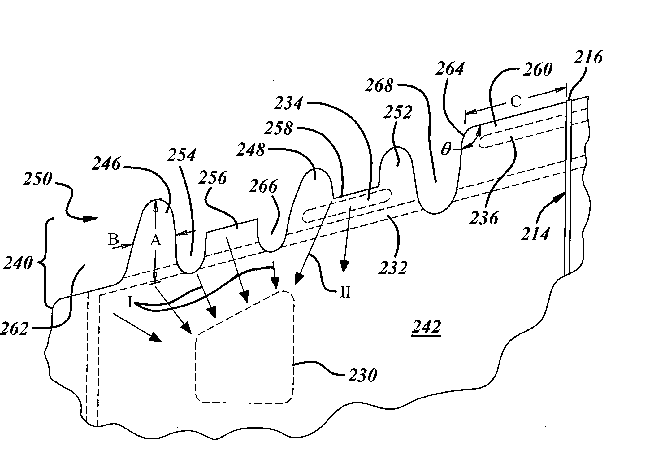
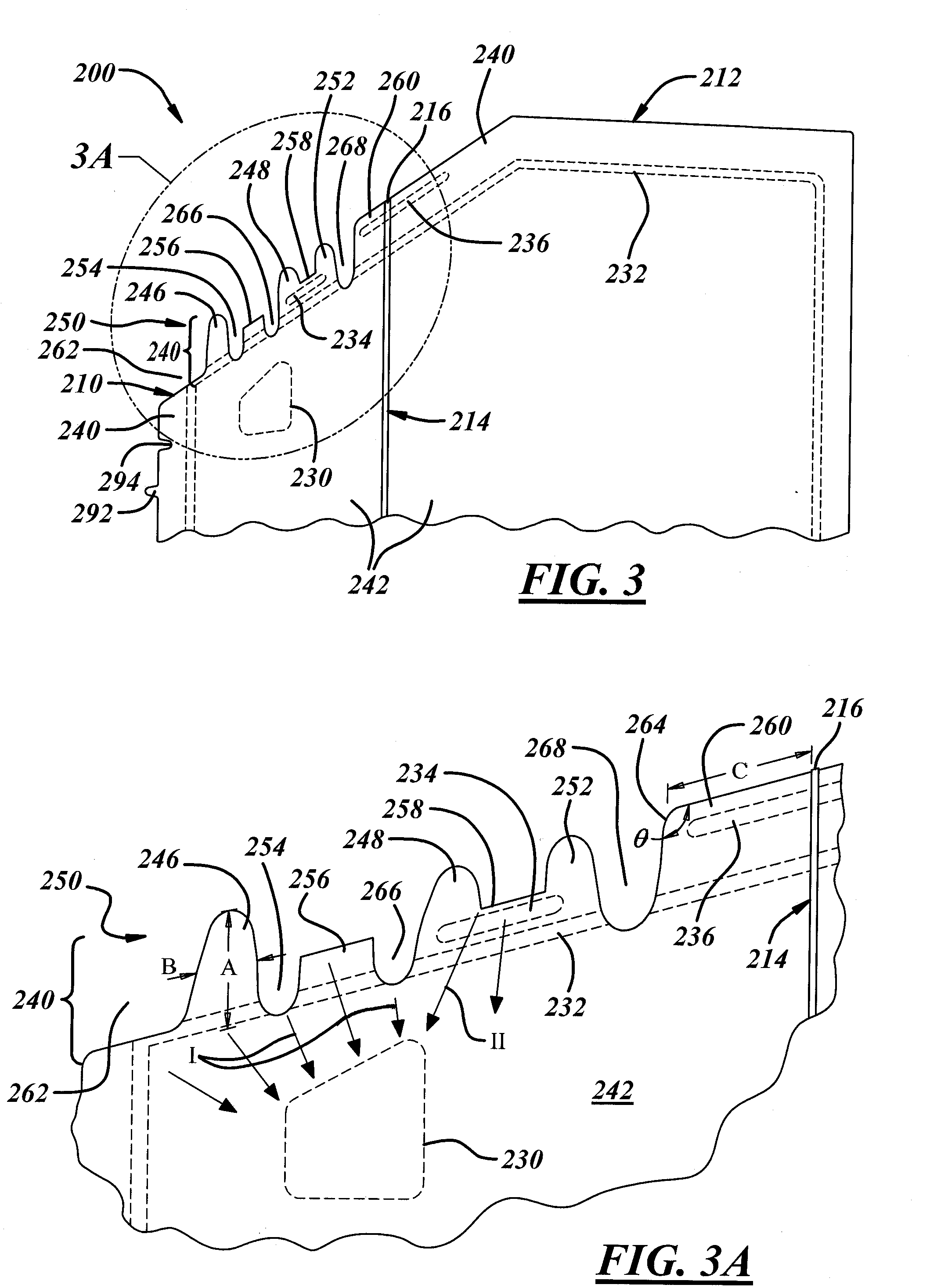
A metal blank that includes a binder trim component having at least one cut edge with a non-linear section. The creation of the non-linear section simultaneously forms a corresponding section in a binder trim component of an adjacent metal blank so that binder material can be shared therebetween. This reduces the amount of scrap metal, as the binder trim component is subsequently cut off and discarded. Furthermore, the non-linear section can include one or more strategically placed formations, such as projections, recesses, flat sections, etc., that cause it to be non-uniform along its length and to be specifically tailored to the manufacturing requirements of the part being formed.

Description

REFERENCE TO RELATED APPLICATIONS[0001]This application claims the benefit of U.S. Provisional Ser. No. 60 / 919,616 filed on Feb. 28, 2007.FIELD OF THE INVENTION [0002]The present invention relates generally to metal blanks, and more particularly, to metal blanks that have a binder trim component and can be used in the automotive industry.BACKGROUND OF THE INVENTION [0003]In the metal forming industry, sheet metal blanks are oftentimes manufactured with an outer flange that extends around the periphery of the sheet metal blank so that during a subsequent metal forming operation, bead structures formed in the upper and lower die will have blank material to engage and clamp onto. The bead structures usually consist of a male bead formed in a binder ring of one of the die and a female groove formed in a binder ring of the other die, and are designed to mate with one another when the upper and lower dies are brought together under the force of a hydraulic or other type of press. By firml...

Claims


Application Information

Patent Timeline
IPC IPC(8): B21D22/22B21D22/10B32B7/02
CPCB21D35/00B21D28/06Y10T428/12389Y10T428/12229Y10T428/12264Y10T428/12201Y10T428/24942B21D22/20B21D22/22
Inventor EWOLSKI, JOHN R.WALTHER, JAMES W.FETSKO, STEPHEN A.
Owner TWB CO LLC
Why Eureka
Try Eureka