Electric Drive System Comprising Differential Steering for a Vehicle, Drive Unit and Vehicle

a technology of electric drive system and differential steering, which is applied in the direction of non-deflectable wheel steering, vehicle components, propulsion parts, etc., can solve the problems of large braking power of heavy tracked vehicles, inability to meet the needs of heavy-duty vehicles, and insufficient installation space of known drive units, so as to achieve the effect of reducing the installation length of the transmission, being light, easy to operate and convenient to us

Inactive Publication Date: 2008-09-04
ZF FRIEDRICHSHAFEN AG
View PDF19 Cites 7 Cited by
  • Summary
  • Abstract
  • Description
  • Claims
  • Application Information

AI Technical Summary

Benefits of technology

[0017]The advantage of this embodiment of the invention is that a composite construction method is achieved in which the electric drive units can be arranged externally. They are then easily accessible for maintenance work, among other things. The offset arrangement of the two drive units opposite to the center axis of the summation gears makes it possible to arrange them where free installation space is available, for example above the crawlers.
[0018]An additional advantage of this embodiment of the invention is that the installation length of the transmission can be considerably reduced.
[0019]If extreme demands are made on both the climbing ability of the vehicle and the maximum speed to be achieved, it is possible to establish a drive connection selectively and with varying shiftable transmission ratios between the first drive unit and the left ring gear and the second drive unit and the right ring gear. The additional cost of the transmission that results from the extra transmission ratios and the necessary shifting elements, such as multiple-plate clutches or dog couplings, pays off because smaller, lighter and more cost-efficient electric drive units can be used.

Problems solved by technology

Heavy tracked vehicles in particular require considerable braking power on the track on the inside of the curve to do this.
However, this known drive unit is very complex and is not optimal in terms of installation space as it requires not only one diesel motor and a complex mechanical, cross-drive, steering transmission, but also a powerful generator and two electric drive units.
This arrangement requires relatively long connecting shafts and is restrictive with regard to compact structural shape.

Method used


Image

  • Electric Drive System Comprising Differential Steering for a Vehicle, Drive Unit and Vehicle
  • Electric Drive System Comprising Differential Steering for a Vehicle, Drive Unit and Vehicle
  • Electric Drive System Comprising Differential Steering for a Vehicle, Drive Unit and Vehicle

Examples


Embodiment Construction

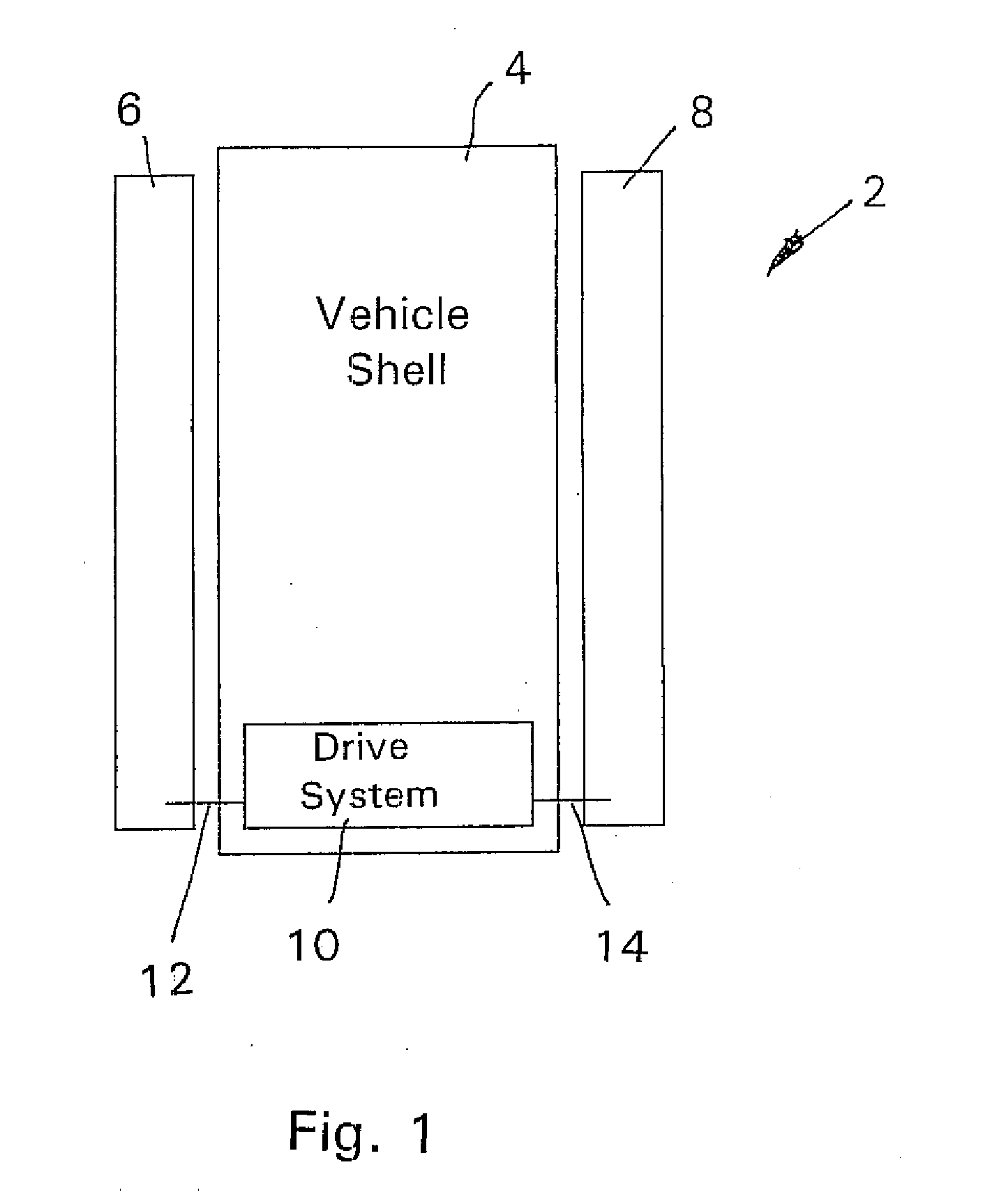
[0027]In FIGS. 1, 2 designates a vehicle with skid steering which, in addition to a shell 4 feature a left crawler 6, a right crawler 8 and an electric drive system 10 whose output shafts 12, 14, drive the two crawlers 6, 8.

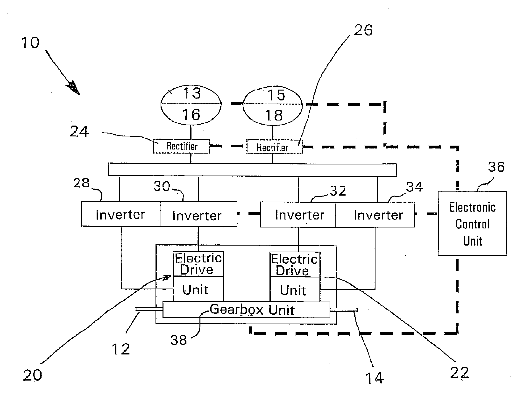
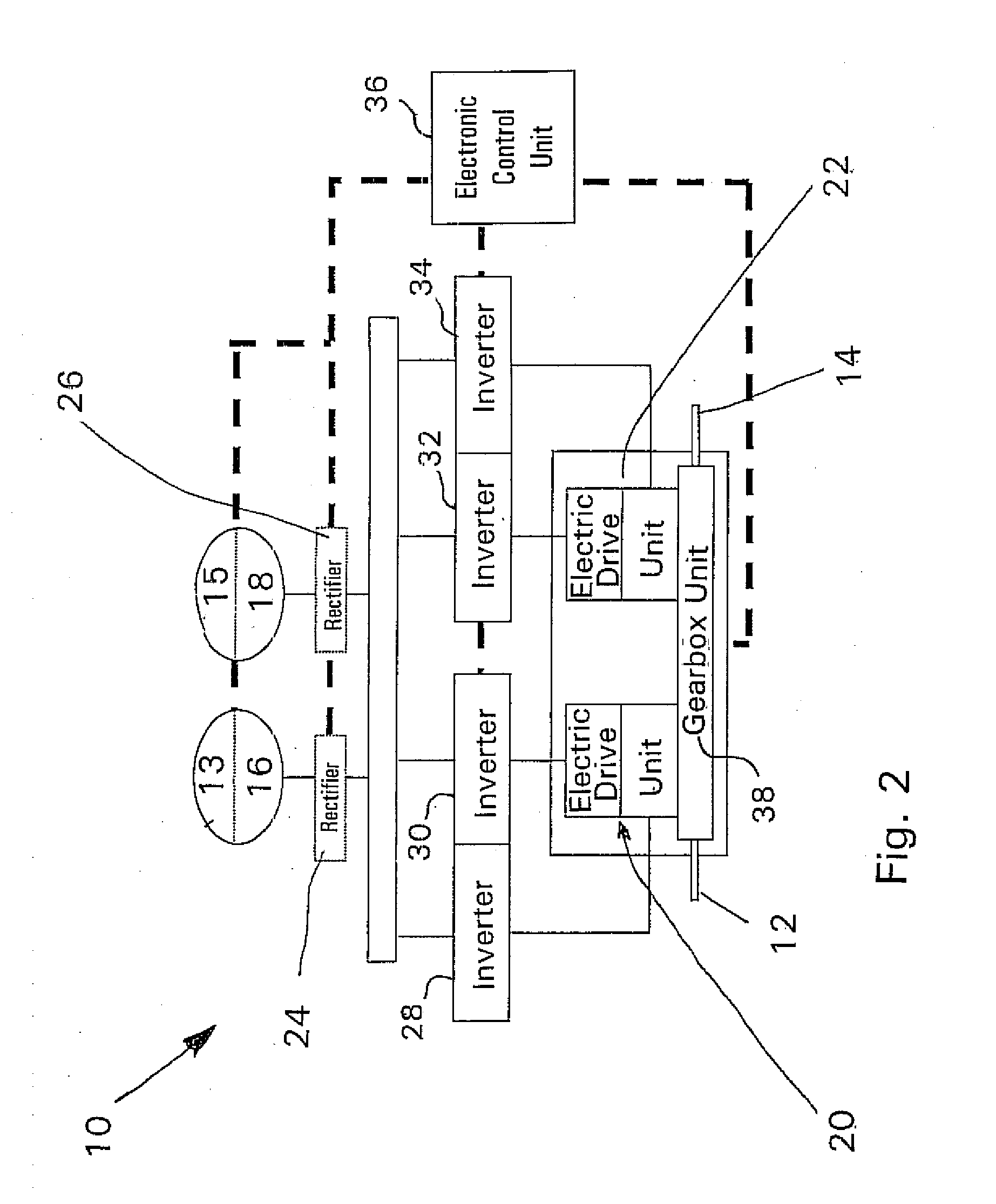
[0028]As shown in FIG. 2, the electric drive system 10 features two similar electric drive units 20, 22, which feature two independent windings that can be controlled independently. A combination of diesel motors 13, 15 and electric generators 16, 18 serve as sources of electric energy. The electric generators 16, 18 are electrically connected to the electric drive units 20, 22 by way of power electronics comprising rectifiers 24, 26, and the inverters 28, 30, 32, 34. The individual components are controlled by an electronic control unit 36 by way of signal lines shown by dotted lines in such a way that independently determined, specified speeds are adjusted for the drive units 20, 22. A gearbox unit 38 features the two output shafts 12, 14 for driving the two cr...


PUM


Abstract

An electric drive system for a vehicle features two similar drive units, an electric energy source, an electronic control unit and a left and a right summation gear, which are configured as planetary gears. A drive unit drives the ring gear of the left summation gear, while the other drive unit drives the ring gear of the right summation gear. The ring gear of the left summation gear has a direct drive connection with the sun gear of the right summation gear, while the ring gear of the right summation gear has a direct drive connection with the sun gear of the left summation gear by way of a second mechanical gearset. A left sun gear shaft is proposed running through a left hollow shaft toward the center of the vehicle and a right sun gear shaft running through a right hollow shaft toward the center of the vehicle.

Description

[0001]This application is a national stage completion of PCT / EP2006 / 005418 filed Jun. 7, 2006, which claims priority from German Application Serial No. 10 2005 027 117.0 filed Jun. 10, 2005.FIELD OF THE INVENTION[0002]The invention relates to an electric drive system for a motor vehicle with skid steering, a gear unit of such a system and a vehicle equipped with it.BACKGROUND OF THE INVENTION[0003]Vehicles with skid steering are tracked vehicles or wheeled vehicles in which, for the purpose of driving in a curve, the track on the inside of the curve or the drive wheels on the inside of the curve, respectively, are decelerated relative to the track on the outside of the curve or the drive wheels on the outside of the curve. Heavy tracked vehicles in particular require considerable braking power on the track on the inside of the curve to do this.[0004]There are different known systems that allow the use of this braking power in that it is fed to the track on the outside of the curve. ...

Claims


Application Information

Patent Timeline
Patent Type & Authority Applications(United States)
IPC IPC(8): B62D11/04
CPCB62D11/04B62D11/02
Inventor BOSS, RALFFREUDENREICH, HANS-PETER
Owner ZF FRIEDRICHSHAFEN AG
Why Eureka
Try Eureka