
Radiometry Using an Uncooled Microbolometer Detector

a microbolometer and detector technology, applied in the field of radiometry using an uncooled microbolometer detector, can solve the problems of blocking the detector field of view of conventional more sophisticated radiometric detectors, unable to meet the uniform incident infrared radiation response of the camera, and building an imaging radiometer

Inactive Publication Date: 2008-09-04
OPGAL
View PDF7 Cites 71 Cited by
  • Summary
  • Abstract
  • Description
  • Claims
  • Application Information

AI Technical Summary

Benefits of technology

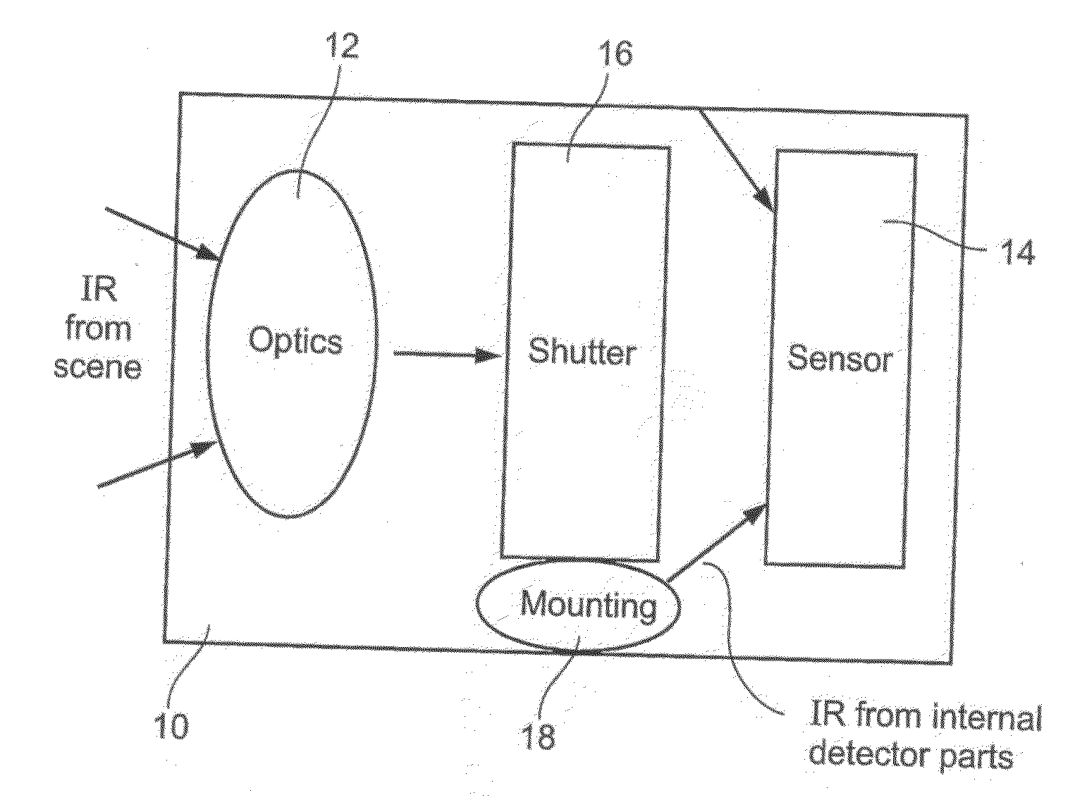
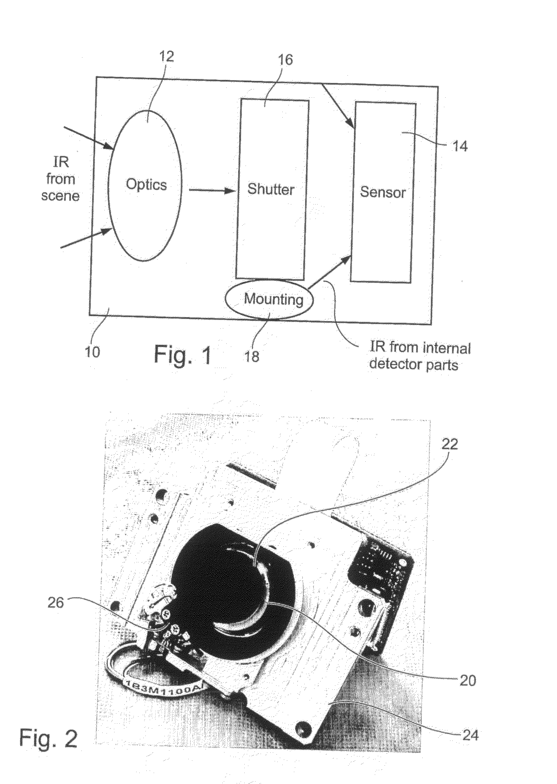
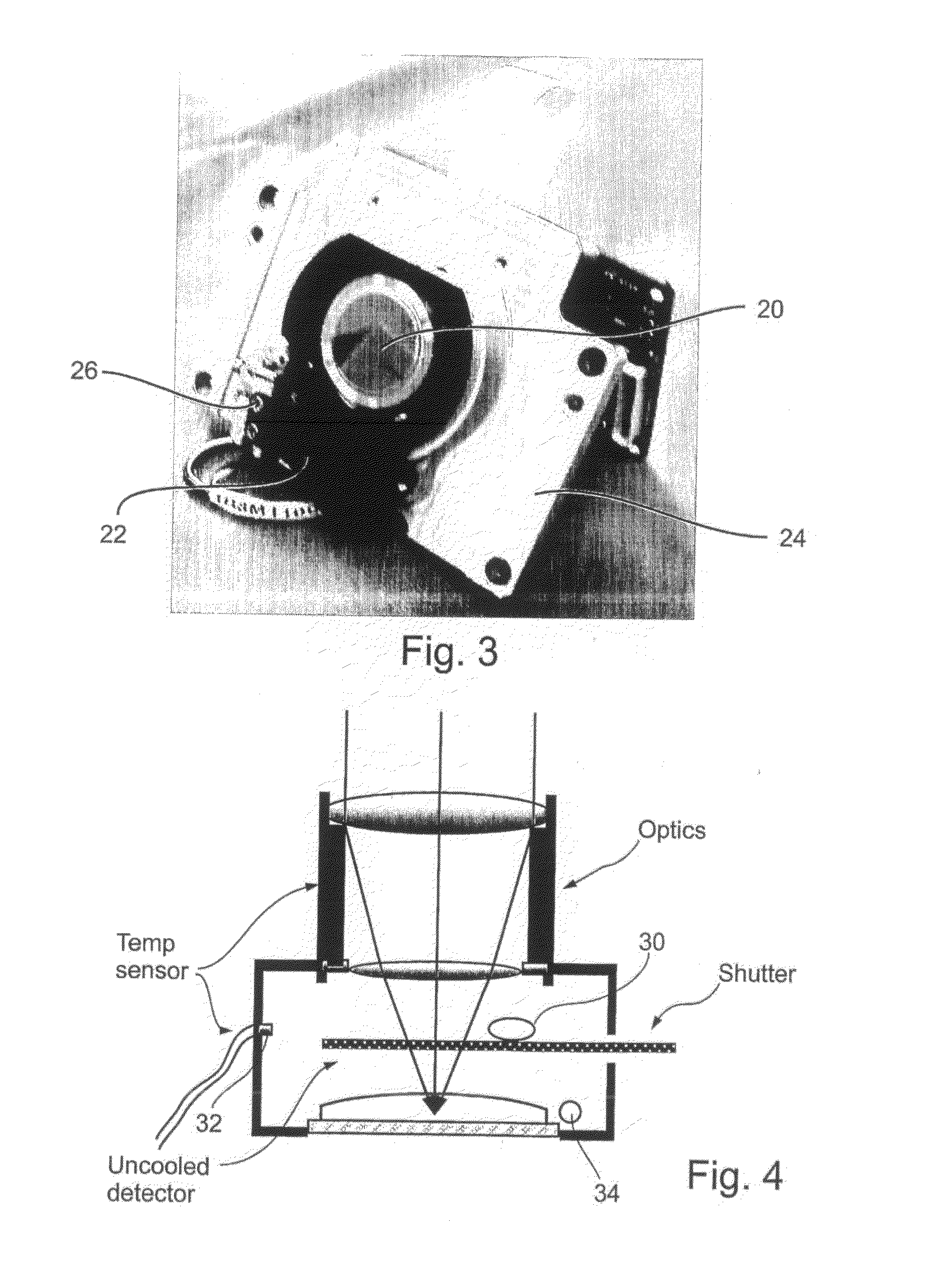
[0035]Preferably, said shutter is mounted such as to have a first stable mechanical position obscuring focusing optics of said camera and a second stable mechanical position allowing free line of sight between said focusing optics and said detector.
[0089]the upgrade comprising applying at least one temperature sensor within said camera for allowing a localized temperature measurement to be taken at periodic intervals for use in calibrating a received image.

Problems solved by technology

FLIR cameras have non-uniform responses to uniform incident infrared radiation.
There are several main obstacles related to building an imaging radiometer, especially when the instrument is based on an uncooled microbolometer detector array.
However, conventional more sophisticated radiometric detectors block the detector field of view using the above mentioned radiation shields.
A very small change in temperature of the internal camera parts therefore may produce a large change of the detector output signal.
Cooled detectors have the disadvantages of greater weight and complexity, as well as additional power consumption for cooling, shorter lifetimes and greater cost.
Overall the cooled devices are used for long range applications and those in which the greater expense can be justified and the uncooled devices are used for medium and short range applications and those in which budgets are limited.
Such an approach is impractical.
An additional problem for imaging IR radiometers is that microbolometer detector arrays generally have a finite spatial response.
More specifically, the translation of the video signal into temperature is subject to an error introduced by the limited modulation transfer function (MTF) response for high spatial frequencies.
A problem is to find a way to upgrade these existing cameras in order to overcome the above-described drawbacks of the uncooled detector to allow them to give accurate temperature measurements under the restriction of very minor hardware modifications.

Method used


Image

  • Radiometry Using an Uncooled Microbolometer Detector
  • Radiometry Using an Uncooled Microbolometer Detector
  • Radiometry Using an Uncooled Microbolometer Detector

Examples


examples

[0217]An implementation of the above-described embodiments was constructed to provide an instrument designed to detect human beings suffering from fever. The instrument monitors the face temperature and any area in the image which is above a predetermined temperature threshold is made to flicker. For such an application the instrument only needs to cover a relatively very small temperature range. A range of 30 to 42 degrees Celsius is more than adequate and can be covered with an accuracy of ±0.25 degrees Celsius. Such an embodiment has applications for use in airports as a convenient and non-invasive detector for screening for carriers of SARS and like infective illnesses.

[0218]The basic concept of temperature measurement using a regular uncooled microbolometer detector is thus provided. The additional hardware required for the temperature measurement capability is limited and inexpensive, thus allowing existing devices to be easily upgraded. It is reasonable to expect that the cap...


PUM


Abstract

An infra-red imaging camera comprises focusing optics for gathering infra-red energy from an external scene, and an uncooled and unshielded detector arranged to detect infra red energy. Internal temperature sensing together with approximation of the temperature response of the camera provides a time varying calibration that allows the infra-red energy received at the detector to be used as a temperature measurement for objects in the camera's field of view.

Description

FIELD AND BACKGROUND OF THE INVENTION[0001]The present embodiments relate to radiometry using an uncooled Microbolometer detector and more particularly but not exclusively to obtaining more accurate results from an uncooled Microbolometer so as to extend its useful range of applications into areas previously only feasible with the more power consuming and more complex vacuum packages. Infra-red (IR) detectors detect the IR radiation emitted from an object, and are used for non-contact measurement of temperatures in many industrial and medical applications. These applications include stress testing electronic components, measuring human temperature, surveillance systems including long range and nighttime surveillance systems, fire detection, and portable night vision equipment.[0002]IR detectors generally operate by detecting the differences in the thermal radiance of various objects in a scene. The difference is converted into an electrical signal which is then processed and analyze...

Claims


Application Information

Patent Timeline
IPC IPC(8): G01J5/02G01J5/52
CPCH04N5/33G01J5/522G01J2005/0077G01J5/0804G01J5/80G01J5/53H04N23/23G01J3/51G01J5/0805
Inventor GRIMBERG, ERNEST
Owner OPGAL
Learn More