Shielding structure of a through-hole formed in a wall of a plastic hollow product

Active Publication Date: 2008-09-04
EX CELL O CORP
View PDF8 Cites 1 Cited by
  • Summary
  • Abstract
  • Description
  • Claims
  • Application Information

AI Technical Summary

Benefits of technology

[0014]One object of the present invention is to provide an improved sealing structure of a plastic hollow product.
[0016]Another object of the present invention to provide an improved sealing structure of a plastic hollow product, which allows to have a component such as a sensor securely mounted in a through-hole formed in a wall of the plastic hollow product.
[0017]Another object of the present invention is to provide a hollow plastic product having an improved sealing structure which is reliable in structure even if subjected to vibration and easy to manufacture.

Problems solved by technology

In this manner, components such as various kinds of sensors are required to be mounted on their desired locations along the air-intake duct, in which case, if the air-intake duct is comprised of a plastic hollow product, since its rigidity is relatively low as compared with a metal, there arises a problem of securing the air-tightness between a sensor and the air-intake duct properly.
In such a case, either one of a nut and a bolt has to be fixed to the air-intake duct; however, if the air-intake duct is comprised of a plastic hollow product, there is difficulty in having a nut or a bolt securely fixed in the plastic hollow product.
Moreover, when a component such as a sensor is mounted in a predetermined position as inserted into a through-hole formed in the air-intake duct, there arises difficulty in sealing the gap between the component and the through-hole.
That is, if the air-intake duct is comprised of a plastic hollow product, it is required to be made to be relatively high in rigidity so that a nut or a bolt can be securely held, but in the case of a plastic hollow product which is relatively high in rigidity, there arises a problem of securely sealing the gap between the component and the through-hole because of constant application of vibration to the air-intake duct during the operation of the engine.

Method used


Image

  • Shielding structure of a through-hole formed in a wall of a plastic hollow product
  • Shielding structure of a through-hole formed in a wall of a plastic hollow product
  • Shielding structure of a through-hole formed in a wall of a plastic hollow product

Examples


Embodiment Construction

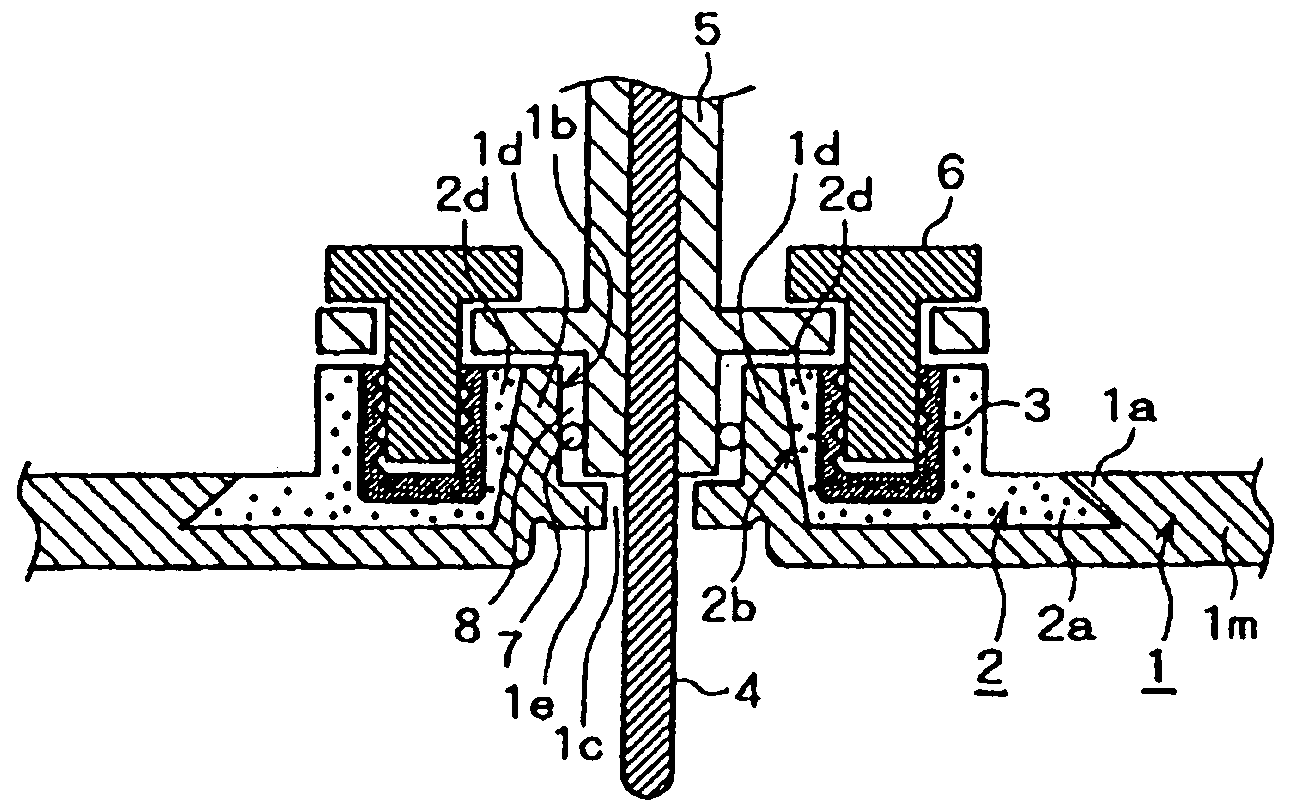
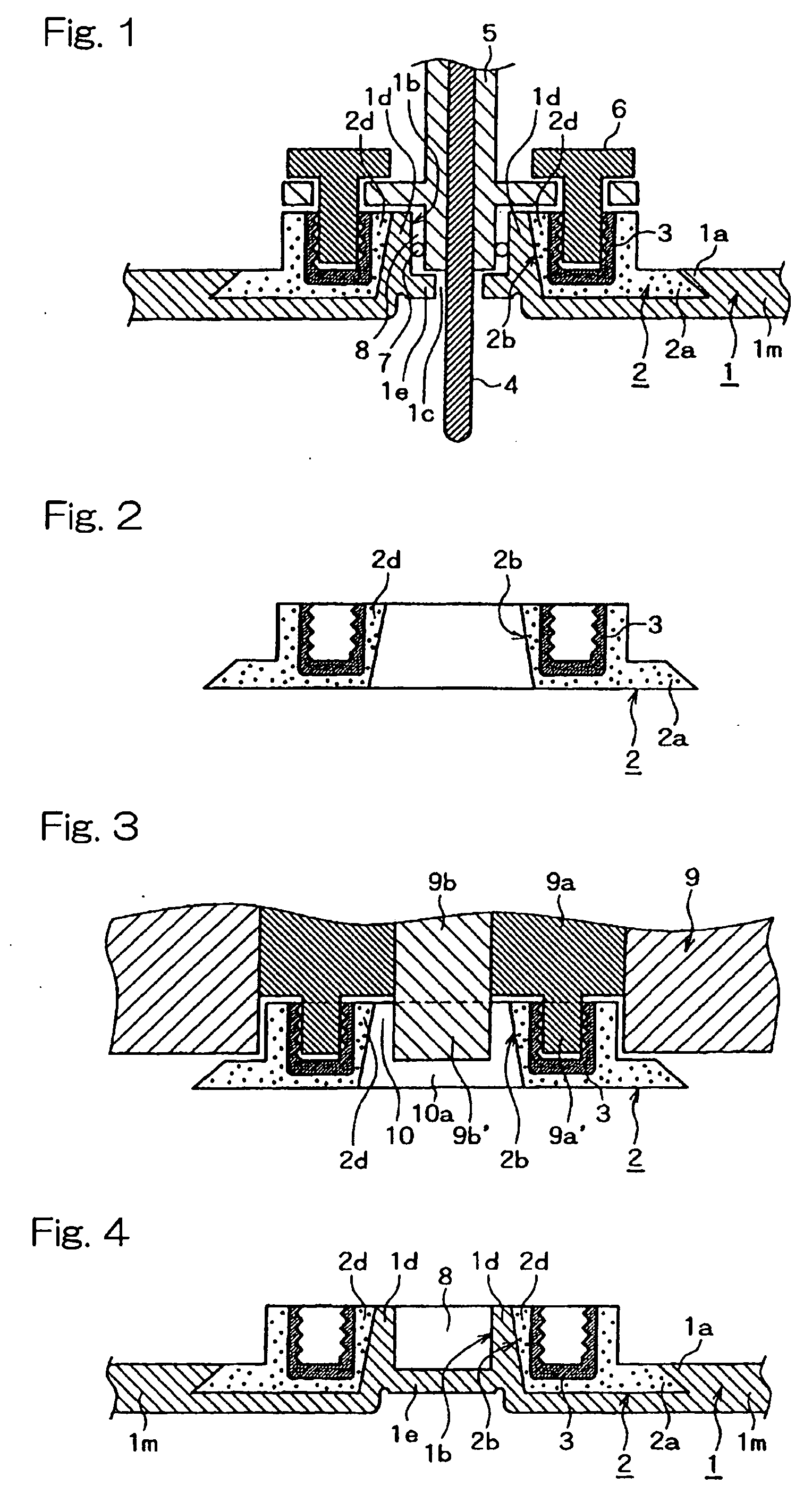
[0031]Referring now to FIG. 1, there is schematically shown a sealing structure of a hollow plastic product 1 suitable for use as an air intake duct of an internal combustion engine for use in an automobile according to one embodiment of the present invention. The plastic hollow product 1 is preferably formed by blow molding from a first resin and includes a peripheral wall 1m which defines a hollow space of a desired shape, such as a duct, pipe or tube. The plastic hollow product 1 is provided with a component mounting member 2, which is preferably comprised of a second resin and integrally molded with the plastic hollow product as an insert when the plastic hollow product 1 is formed by blow molding. During blow molding of the plastic hollow product 1 with the component mounting member 2 as an insert, an interface therebetween is subjected to a thermal adhesion reaction so that these two are integrated together. Moreover, in the instant embodiment, as shown in FIG. 1, the peripher...


PUM

PropertyMeasurementUnit
Structureaaaaaaaaaa
Shapeaaaaaaaaaa
Stiffnessaaaaaaaaaa

Abstract

An improved structure for sealing a through-hole formed in a plastic hollow product when mounting a component such as a sensor on the product is provided. A cylindrical section is provided in a peripheral wall of the plastic hollow product as projecting radially outwardly from the peripheral wall and an inner circumferential surface of the cylindrical section defines the through-hole for communication between the interior and the exterior of the product. A sensor component is mounted with its sensor portion extending through the through-hole and an O-ring is disposed between the sensor portion and the inner circumferential surface of the cylindrical section which is backed by a component mounting member.

Description

BACKGROUND OF THE INVENTION[0001]1. Field of the Invention[0002]This invention generally relates to a shielding structure of a through-hole formed in a plastic hollow product and in particular to a shielding structure in the case when a through-hole is formed in a duct, such as a duct of an air-intake system of an automobile engine, for detecting its interior environment and a sensor is located in the through-hole.[0003]2. Description of the Prior Art[0004]Heretofore, in the case of providing a through-hole in a wall of a plastic hollow product and providing a branch pipe in communication with the interior space of the hollow product via the through-hole, a technology for securing air-tightness between the hollow product and the branch pipe was known. For example, Japanese Patent Laid-open Pub. No. Sho 64-56532, assigned to the assignee of this application, discloses a sealing technology in which the sealing characteristic is improved between the plastic hollow product and the branc...

Claims


Application Information

Patent Timeline
IPC IPC(8): F01D13/02
CPCB29C49/04B29C49/20B29C2049/2017B29L2031/3005B29C2049/2069B29L2023/004B29C2049/2043
Inventor NAKAGAWA, TATSUYATAMURA, TAKASHI
Owner EX CELL O CORP
Why Eureka
Try Eureka