Electronic imaging device and driving method therefor

Active Publication Date: 2008-09-04
SAMSUNG DISPLAY CO LTD
View PDF2 Cites 20 Cited by
  • Summary
  • Abstract
  • Description
  • Claims
  • Application Information

AI Technical Summary

Benefits of technology

[0009]Aspects of embodiments of the present invention are directed to an electronic imaging device and/or a dr

Problems solved by technology

However, the operation at the higher driving frequency causes an increase in power consumption of the electronic imag

Method used


Image

  • Electronic imaging device and driving method therefor
  • Electronic imaging device and driving method therefor
  • Electronic imaging device and driving method therefor

Examples


Example

[0032]In the following detailed description, only certain exemplary embodiments of the present invention have been shown and described, simply by way of illustration. As those skilled in the art would realize, the described embodiments may be modified in various different ways, all without departing from the spirit or scope of the present invention. Accordingly, the drawings and description are to be regarded as illustrative in nature and not restrictive. Like reference numerals designate like elements throughout the specification.

[0033]Throughout this specification and the claims that follow, when it is described that a first element is “coupled” or “connected” to a second element, the first element may be “directly coupled” or “directly connected” to the second element or be “electrically coupled” or “electrically connected” to the second element through one or more other elements. In addition, unless explicitly described to the contrary, the word “comprise”, and variations such a...


PUM


Abstract

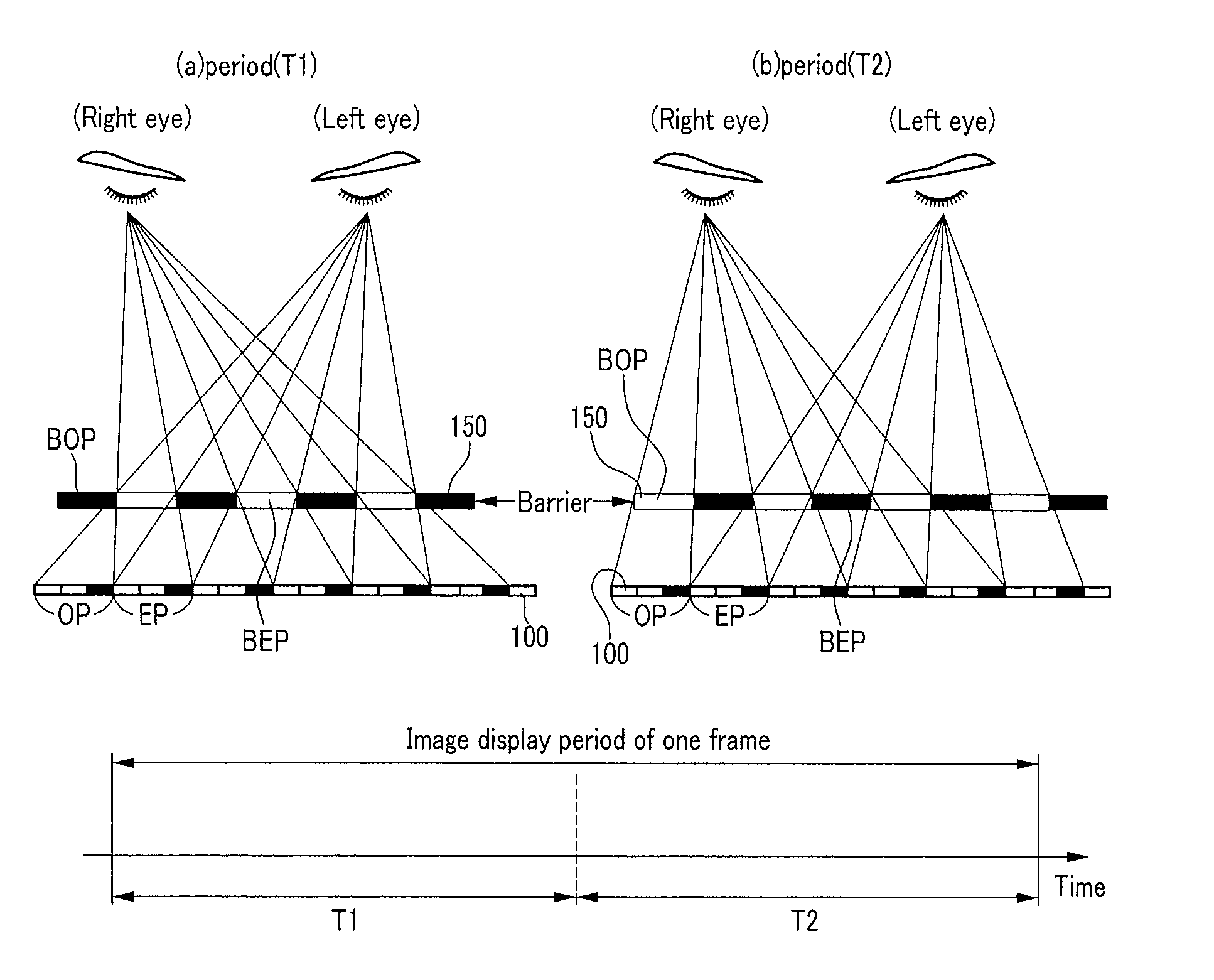
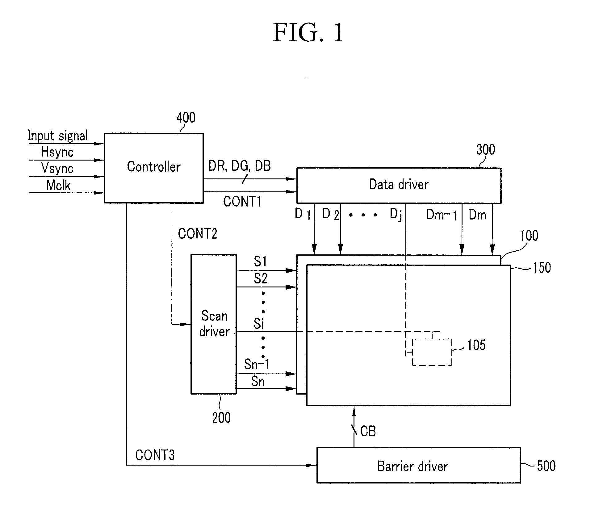
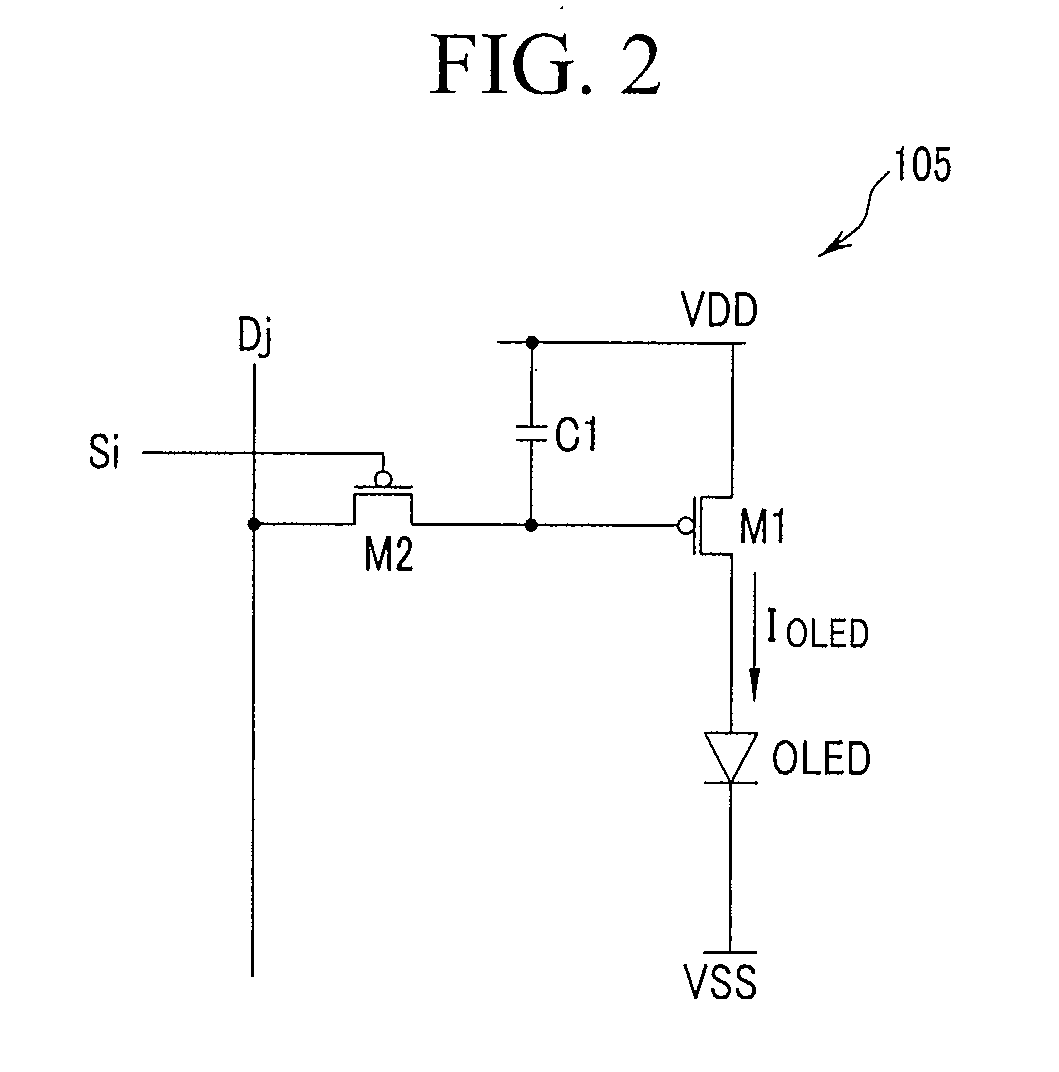
An electronic imaging device includes a display unit and a barrier layer. The display unit includes scan lines for transferring select signals, data lines for transferring data signals corresponding to first and second images formed according to one or more input signals, and pixels connected with the scan and data lines. The barrier layer includes first barriers and second barriers corresponding to the first barriers. The first image is displayed during a first period of a unit period during which an image of a single frame is displayed. The second image is displayed during a second period different from the first period. The first barriers are driven according to the first image, the second barriers are driven according to the second image, and a region of the barrier layer corresponding to a mixed region in which the first and second images coexist is a non-transmission region.

Description

CROSS-REFERENCE TO RELATED APPLICATION[0001]This application claims priority to and the benefit of Korean Patent Application No. 10-2007-0021137 filed in the Korean Intellectual Property Office on Mar. 2, 2007, the entire content of which is incorporated herein by reference.BACKGROUND OF THE INVENTION[0002]1. Field of the Invention[0003]The present invention relates to an electronic imaging device, and more particularly, to an electronic imaging device capable of displaying stereoscopic images.[0004]2. Description of the Related Art[0005]In general, humans perceive a stereoscopic effect based on physiological and experiential factors, and three-dimensional image displaying technologies express a stereoscopic effect of an object by using binocular parallax, which is a key factor for allowing humans to recognize a stereoscopic effect at a short distance.[0006]Typically, an electronic imaging device that displays stereoscopic images use a method in which left and right images are spati...

Claims


Application Information

Patent Timeline
IPC IPC(8): G02F1/133G02B30/31
CPCG02B27/2214G09G3/001G09G3/003G09G3/20G09G3/3611G09G3/36G09G2300/023H04N13/0409G09G3/3233H04N13/31G02B30/31H05B33/22G02F1/133G02B30/27
Inventor NAM, HUIKIM, BEOM-SHIKPARK, CHAN-YOUNGKU, JA-SEUNG
Owner SAMSUNG DISPLAY CO LTD
Why Eureka
Try Eureka