Inspection and strength measurement of solder and structural joints using laser generated stress waves

Inactive Publication Date: 2008-09-04
RGT UNIV OF CALIFORNIA
View PDF7 Cites 6 Cited by
  • Summary
  • Abstract
  • Description
  • Claims
  • Application Information

AI Technical Summary

Benefits of technology

[0012]An aspect of the invention is a method for measuring the tensile strength of a solder joint disposed between a solder ball and an underlying structure. The method includes the steps of directing a laser pulse at a first surface in communication with the solder joint, and generating

Problems solved by technology

However, under high temperature environments, IMC growth can become excessive.
This results in brittle interfaces and deteriorates the mechanical integrity o

Method used


Image

  • Inspection and strength measurement of solder and structural joints using laser generated stress waves
  • Inspection and strength measurement of solder and structural joints using laser generated stress waves
  • Inspection and strength measurement of solder and structural joints using laser generated stress waves

Examples


Embodiment Construction

[0049]Referring more specifically to the drawings, for illustrative purposes the present invention is embodied in the apparatus generally shown in FIG. 3 through FIG. 21. It will be appreciated that the apparatus may vary as to configuration and as to details of the parts, and that the method may vary as to the specific steps and sequence, without departing from the basic concepts as disclosed herein.

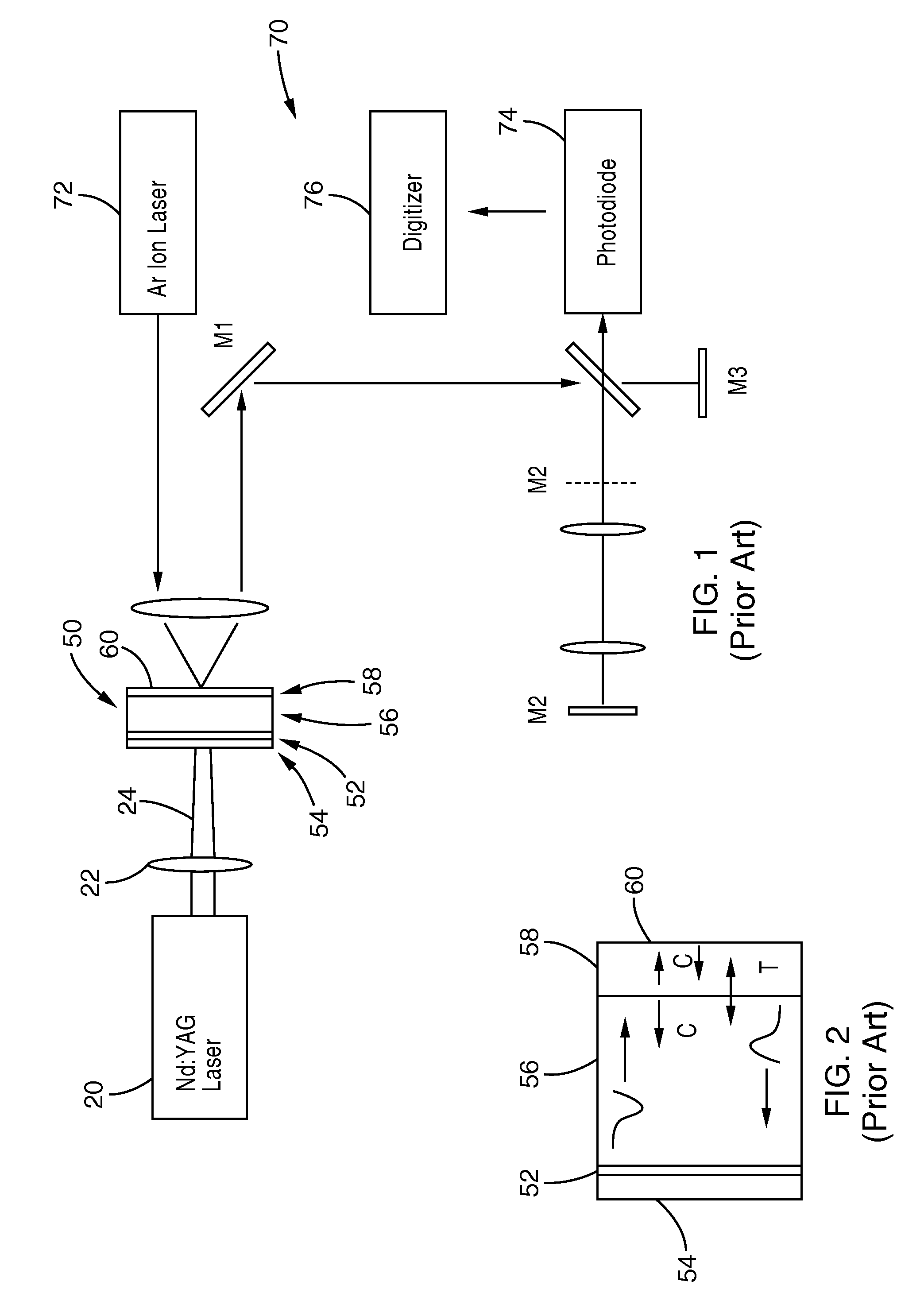
[0050]FIG. 1 illustrates a setup using laser spallation techniques, which are described in more detail in U.S. Pat. No. 5,438,402, incorporated herein by reference in its entirety. A 3-nanoseconds (ns) long Nd:YAG laser pulse is directed at sample assembly 50 and made to impinge over a 3 mm-diameter area on a 0.5 μm thick aluminum film 52 that is sandwiched between the back surface of a substrate disc (having a 12-25 mm diameter and 1-mm thickness) and a 10 to 20 μm thick layer of SiO2.

[0051]When actuated, the first input laser 20 generates a laser pulse that passes along the first axis...


PUM

PropertyMeasurementUnit
Magnetic fieldaaaaaaaaaa

Abstract

Methods and apparatus are disclosed for direct measurement of the tensile strength of joints with use of laser spallation. A laser pulse is directed at a surface in communication with a solder joint, generating a stress wave to separate the solder ball from its underlying structure. The solder joint may be measured either prior to joining of a PCB board or CSP package, or after they have been joined. The joints for testing may be prepared by polishing either the PC board or the CSP package to expose the desired solder joint for testing. The tensile strength of the embedded joints may also be measured in-situ.

Description

CROSS-REFERENCE TO RELATED APPLICATIONS[0001]This application claims priority from, and is a 35 U.S.C. §111(a) continuation-in-part of, co-pending PCT international application serial number PCT / US2006 / 005896, filed on Feb. 17, 2006, incorporated herein by reference in its entirety, which claims priority from U.S. provisional application Ser. No. 60 / 654,187 filed on Feb. 17, 2005, incorporated herein by reference in its entirety.[0002]This application is related to PCT International Publication Number WO / 2006 / 089257, published on Aug. 24, 2006, incorporated herein by reference in its entirety.STATEMENT REGARDING FEDERALLY SPONSORED RESEARCH OR DEVELOPMENT[0003]This invention was made with Government support under Grant No. DMI-0323804, awarded by the National Science Foundation and Grant No. DAAD19-00-1-0491, awarded by the Army Research Office (ARO). The Government has certain rights in this invention.INCORPORATION-BY-REFERENCE OF MATERIAL SUBMITTED ON A COMPACT DISC[0004]Not Appli...

Claims


Application Information

Patent Timeline
IPC IPC(8): G01L1/24
CPCB23K31/02G01N3/00G01N29/2418G01N2291/0421G01N2203/005G01N2203/0057G01N2203/0296G01N2203/001
Inventor GUPTA, VIJAY
Owner RGT UNIV OF CALIFORNIA
Why Eureka
Try Eureka