
Method and Device for Management of Flow in a Packet-Telecommunication Network

a packet-telecommunication network and flow management technology, applied in data switching networks, instruments, frequency-division multiplexes, etc., can solve problems such as detection of new, increase in the time to look up flow in the list, and risk of saturation, and achieve simple software and hardware implementation.

Inactive Publication Date: 2008-09-04
FRANCE TELECOM SA
View PDF5 Cites 6 Cited by
  • Summary
  • Abstract
  • Description
  • Claims
  • Application Information

AI Technical Summary

Benefits of technology

[0021]Thus the flow management method of the invention is based on a data structure of fixed size, with each flow being addressable directly. This feature advantageously limits the time taken to look up a flow in the structure, and also ensures lookup time is constant.
[0025]It is very advantageous if the data structure is read by addressing the register of the flow concerned directly during the determination step. This direct addressing mode avoids the requirement to store the identifier of the flow in the data structure and simplifies the operation of looking up the flow. Furthermore, the invention dispenses with identifying flows that are no longer active and eliminating them. In the invention, a new flow might not be recognized as such if another active flow is already using the corresponding flow register (this constitutes a “false positive” type error).
[0035]This second variant has the advantages that it lends itself to simple software and hardware implementation and accommodates the use of a standard memory (organized into words of 8×n bits) for storing the flow registers.

Problems solved by technology

The problem of detecting new flows arises in the context of a “flow aware” network architecture.
That mechanism has the drawback that it is necessary to delete flows from the list at the end of an inactivity time greater than the flow time-out period, failing which there would be a risk of saturation and, in any event, an increase in the time to look up a flow in the list.

Method used


Image

  • Method and Device for Management of Flow in a Packet-Telecommunication Network
  • Method and Device for Management of Flow in a Packet-Telecommunication Network
  • Method and Device for Management of Flow in a Packet-Telecommunication Network

Examples


Embodiment Construction

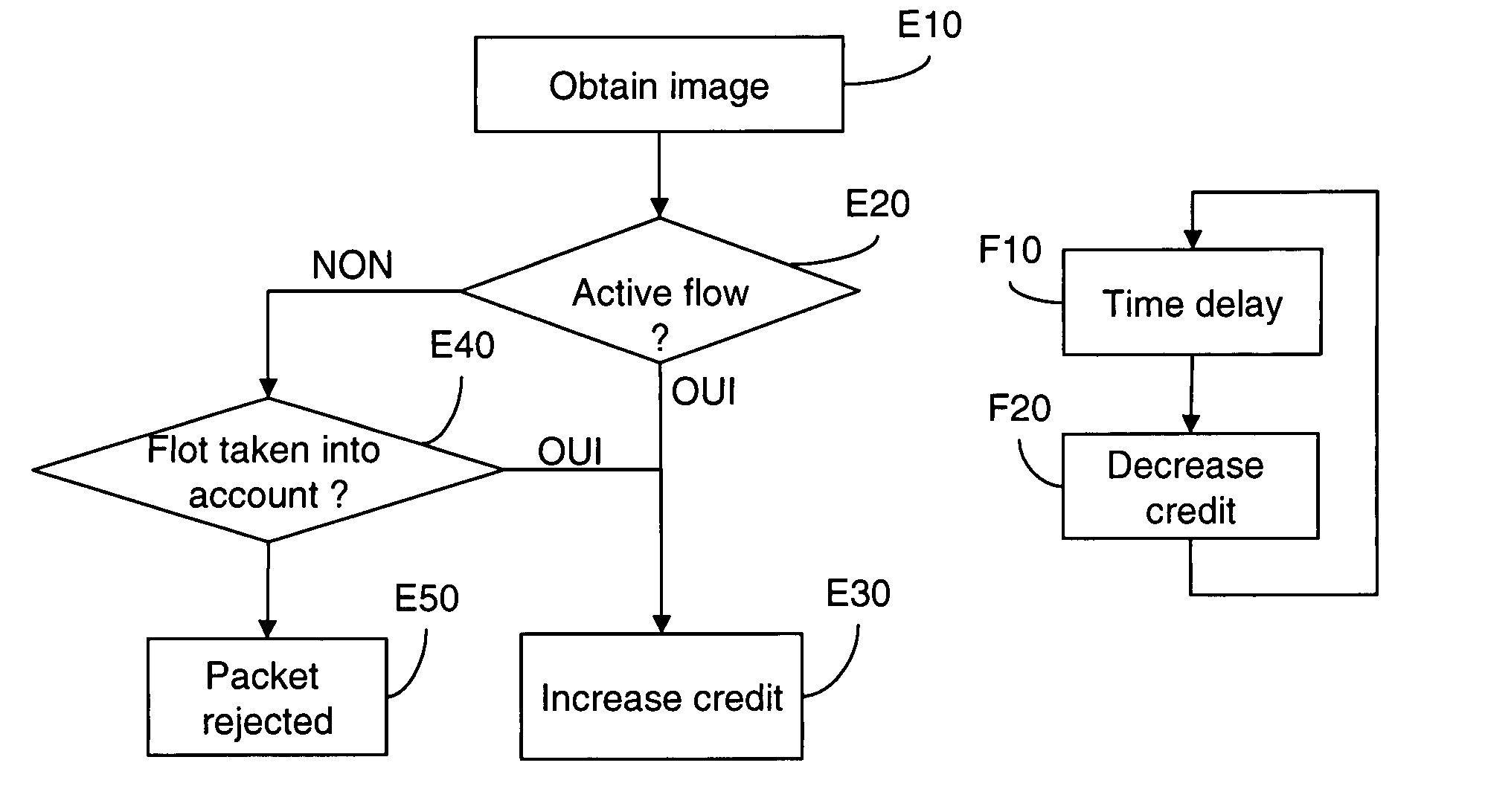
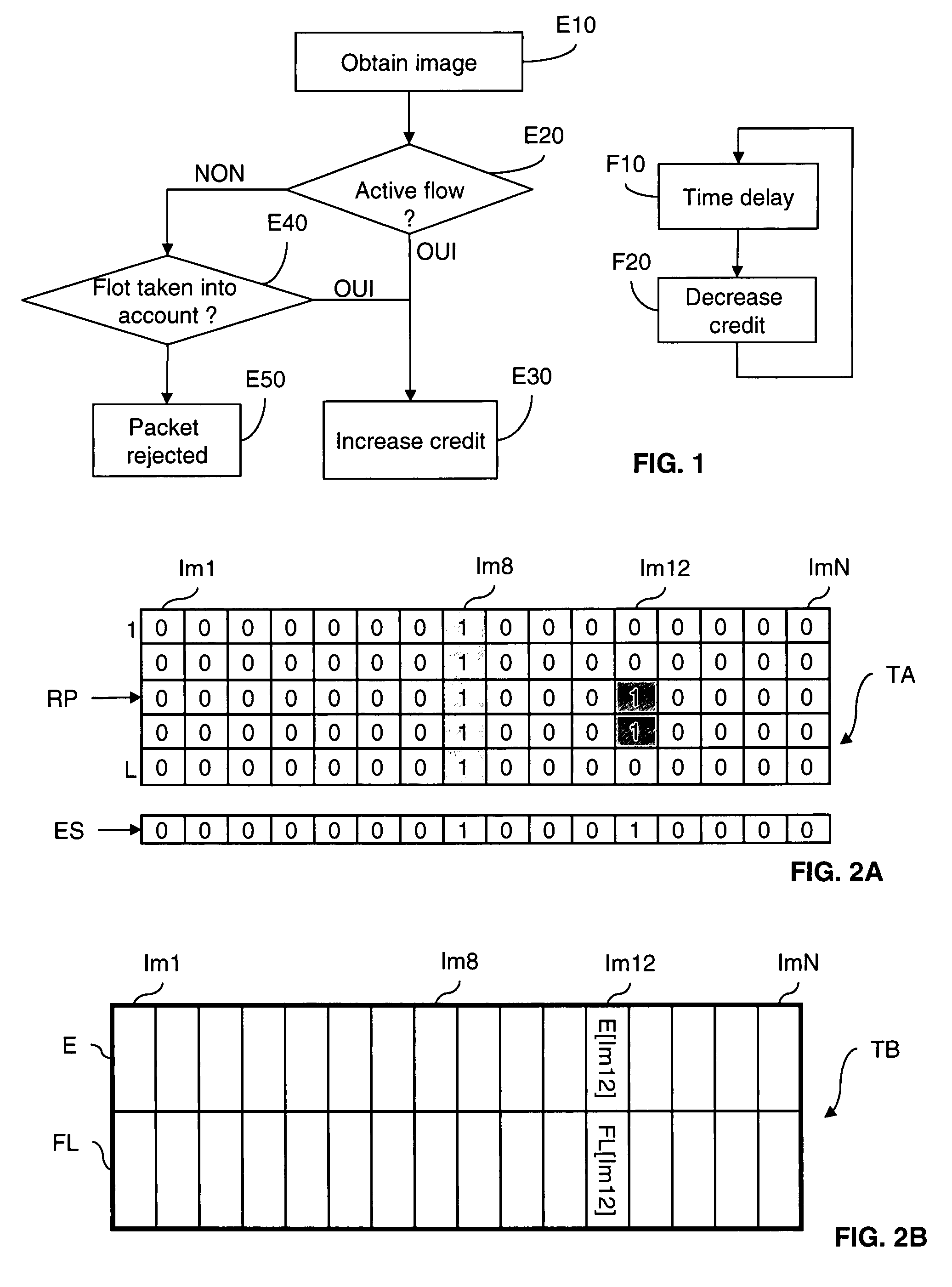
[0053]FIG. 1 represents a flow management method according to the invention.

[0054]A flow is defined here as a series of packets that are closely spaced in time and have common header attributes (IP address, protocol, port number, flow label, etc.).

[0055]A flow is considered to be active in the network if the time that has elapsed since detection of the last packet of that flow is less than a predetermined time-out period TO.

[0056]In the preferred implementation described here, this method includes two independent processes, namely an initialization process, which is executed on detecting a packet of a flow that is to be taken into account, and an updating process.

[0057]In FIG. 1 there are shown, in the form of flowcharts:

[0058]the main steps E10 to E50 of the initialization process; and

[0059]the main steps F10 and F20 of the updating process.

[0060]The management method according to the invention described here uses a fixed-size data structure.

[0061]A first variant of the management ...


PUM


Abstract

This A flow management method includes a step (E10) of computing an image value of a flow identifier; a step (E30) of initializing a credit representing the activity of the flow in a directly addressable register of a data structure (TA, TB); and a step (F20) of updating that credit, systematically, so that the credit of the flow expires at the end of a predetermined time-out period (TO).

Description

BACKGROUND OF THE INVENTION[0001]The present invention relates to a method of flow management in a packet-switched telecommunications network, more particularly in a network implementing the Internet Protocol (IP).[0002]Although this is not limiting on the invention, the invention applies especially to methods used to meet the requirements of a flow-level admission control mechanism.[0003]In the context of the present invention, a flow is identified by a set of attributes present in the header of the packets that constitute it (examples of attributes are source and destination IP addresses, source and destination ports, protocol, flow label, etc.).[0004]All packets having the same values of these attributes constitute a flow.[0005]At any given time, a flow is considered to be active if the time that has elapsed since observation of its last packet is less than a predetermined time-out period (which is typically of the order of a few seconds).[0006]The invention proposes a solution f...

Claims


Application Information

Patent Timeline
Patent Type & Authority Applications(United States)
IPC IPC(8): H04L1/00
CPCH04L45/00H04L45/54H04L47/39H04L47/2483H04L47/32H04L47/10
Inventor OUESLATI, SARAHROBERTS, JAMESBENAMEUR, NABIL
Owner FRANCE TELECOM SA
Learn More