Resurfacing-Hip Implant Construction Set

a technology for resurfacing and hip implants, applied in the field of resurfacing hip implants, can solve the problems of negative impact on long-term fixation, and achieve the effects of preventing any cap turning, precise positioning of the cup, and increasing the stability of the cap

Inactive Publication Date: 2008-09-04
ESKA IMPLANTS GMBH & CO
View PDF7 Cites 8 Cited by
  • Summary
  • Abstract
  • Description
  • Claims
  • Application Information

AI Technical Summary

Benefits of technology

[0019]In the pole region of the cup of the acetabulum, an opening can beneficially be provided, through which a positioning aid can be placed. This positioning aid might for example be a blind screw which, once inserted, can grip onto the base of the socket for an extended period. This performs a guiding function which enables the precise positioning of the cup in the acetabulum.
[0020]Particularly preferential would be a further elaboration meaning that, on the inside of the cap for the femoral head, at least two anti-rotation elements protrude into the inside of the cap. This increases the stability of the cap on the femoral head. The anti-rotation elements, once implanted, protrude into the bone of the femoral head, thus preventing any turning of the cap on the femoral head.

Problems solved by technology

In general, necrosis of the head of the joint can lead to surface abnormalities which however still do not justify completely removing the head of the joint, and fitting the patient with a short-stemmed endoprosthesis (EP 0 878 176).
So bone material is always freshened, which leads to bleeding, which, among other things, can have a negative impact on long term fixation.

Method used


Image

  • Resurfacing-Hip Implant Construction Set
  • Resurfacing-Hip Implant Construction Set
  • Resurfacing-Hip Implant Construction Set

Examples


Embodiment Construction

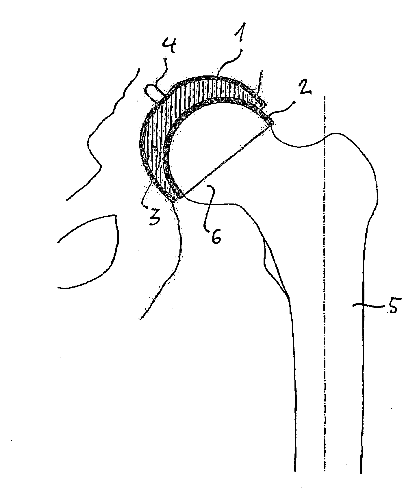
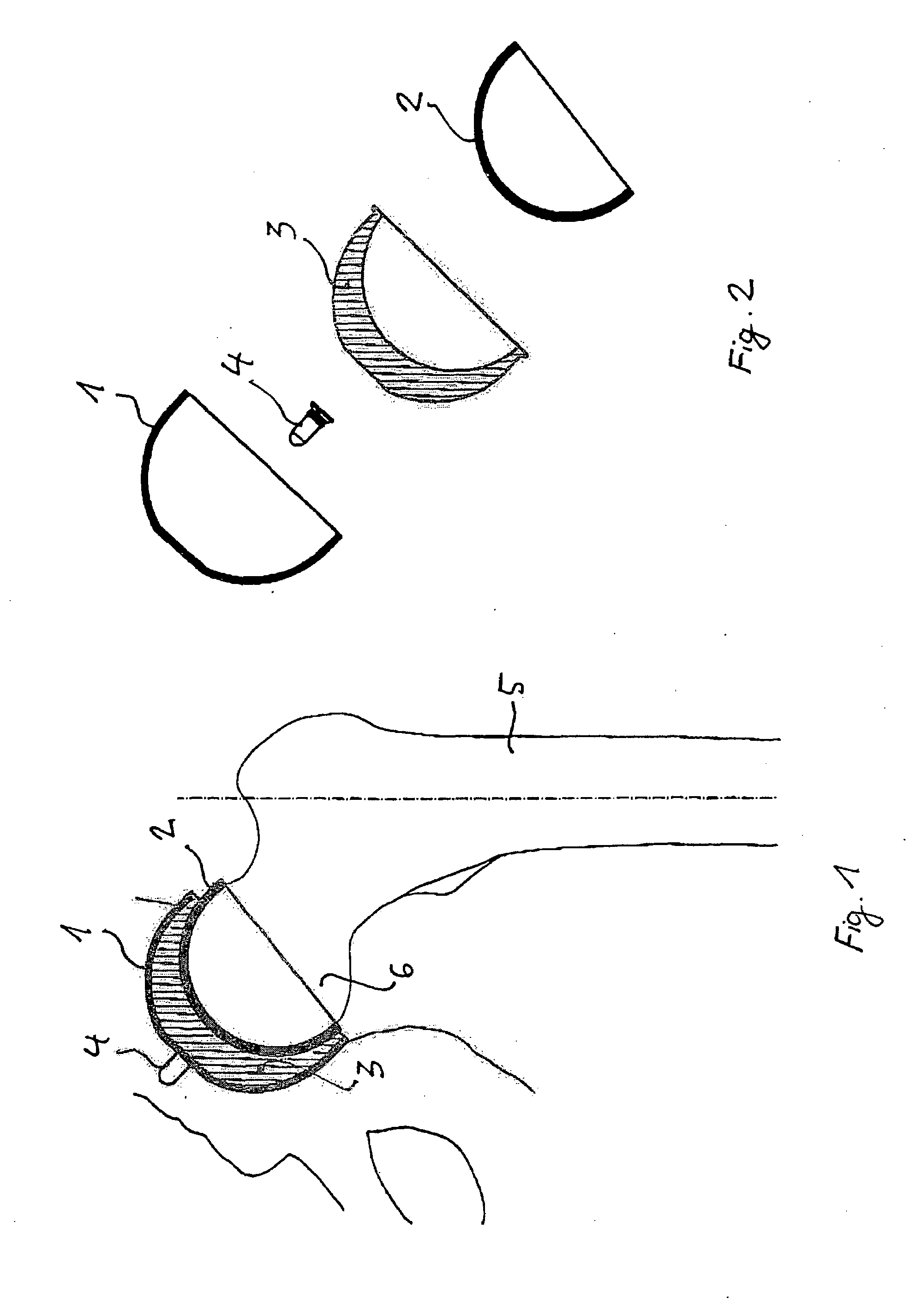
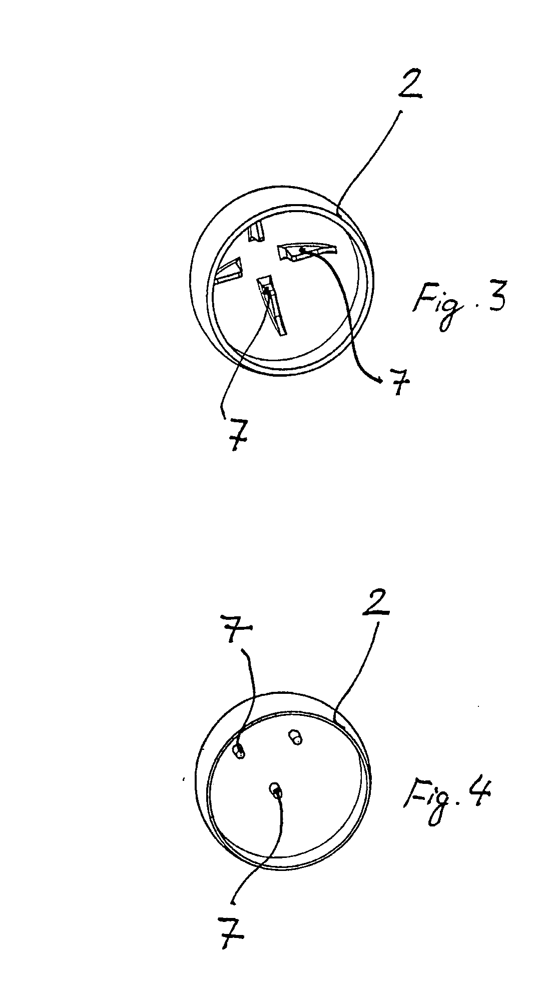
[0028]FIG. 1 schematically illustrates how the hip implant, which has been constructed from the set, is implanted. Metal cap 2 is placed on the femoral head 6 of the femur 5. It is fixed there with a thin layer of cement on the inside of the cap.

[0029]The metal cup 1 is placed in the natural acetabulum 7 and fixed there with a thin layer of cement. The cement used is a very thin liquid.

[0030]Inlay 3 is placed in cup 1, which forms the sliding partner for metal cap 2. A positioning aid protrudes into the hip bone, this might for example be a blind screw, which is inserted through an opening in the pole region of cup 1, and protrudes from there into the hip bone.

[0031]In the construction of the resurfacing hip implant, firstly the positioning aid 4 is placed through the opening in the pole region of cup 1 (FIG. 2). Then comes the insertion of inlay 3 into cup 1. The inlay 3 sits in cup 1 in a (conical) press fit and is replaceable. A specially designated cap 2 is then selected to plac...


PUM

PropertyMeasurementUnit
thickaaaaaaaaaa
thicknessaaaaaaaaaa
thicknessaaaaaaaaaa

Abstract

Described here is a set for the construction of a resurfacing hip implant. It comprises a thin metal cup for cemented insertion into the natural acetabulum, a thin metal cap for cemented placement upon the natural femoral head, and an inlay which can be placed in the cup of the acetabulum as a sliding partner for the cap for the femoral head.

Description

BACKGROUND OF THE INVENTION[0001]1. Field of the Invention[0002]The invention concerns a set for constructing a resurfacing hip implant. This is understood to mean a surface replacement of the natural sliding or articulation surfaces of the acetabulum and the head of the femur.[0003]2. Description of Related Art[0004]Recently, there has been an increase in the use of so called cap implants, which are placed over the readily-prepared residual femoral head, and which can then be fixed in this position. Cap implants consist of a cap modelled on the external form of the natural ball joint, which can be placed on the (part-) prepared residual natural head of the joint. An implant of this type can be constructed from the so-called set for the construction of a reinforcing implant according to DE-C-102 18 801.[0005]To ensure a stable secondary fixation, it is necessary that the bone matter of the residual bone is stable. For this reason, the aforementioned document suggests connecting a pi...

Claims


Application Information

Patent Timeline
Patent Type & Authority Applications(United States)
IPC IPC(8): A61F2/32A61F2/36
CPCA61F2/32A61L27/50A61F2/3603A61F2002/30324A61F2002/30332A61F2002/30405A61F2002/30604A61F2002/3404A61F2002/3414A61F2002/4631A61F2220/0025A61F2220/0033A61F2250/0036A61F2310/00011A61F2310/00179A61F2310/00592A61L27/28A61F2/34A61F2002/3403
Inventor GRUNDEI, HANSGERDESMEYER, LUDGER
Owner ESKA IMPLANTS GMBH & CO
Why Eureka
Try Eureka