Method and system of calibrating sensing components in a circuit breaker system

a circuit breaker and component technology, applied in the direction of testing circuits, protective devices, instruments, etc., can solve the problems of affecting the production efficiency affecting the quality of circuit breaker components,

Active Publication Date: 2008-09-04
SQUARE D CO
View PDF8 Cites 52 Cited by
  • Summary
  • Abstract
  • Description
  • Claims
  • Application Information

AI Technical Summary

Benefits of technology

[0008]The calibration of the product is extended to the design process rather than just to the manufacturing process. Calibration responsibility can be seamlessly integrated between the manufacturing and design functions. In addition, the calibration techniques disclosed herein store the nominal templates during the design process at high temperatures, such as 90° C., and scaling is performed on this elevated nominal calibration template. An advantage of high temperature calibration is that the circuit breaker will be less prone to nuisance tripping when errors occur in the temperature calibration system.
[0010]A test current is independently injected into each of the three current transformers from the functional tester and the response of the current transformers is read from the microcontroller. The responses of the current transformers to the injected currents, and the temperature of the circuit board are used to scale the characteristic curves of the transformer to provide a curve that will fit the system as a whole, i.e., the current transformers and the circuit board. This process eliminates error from the voltage reference, some of the A / D error, and error associated with the burden resistor and FET Rds,on.

Problems solved by technology

A circuit breaker may be tripped by an overload or short circuit, which causes an interruption of power to the load.
This method has the disadvantage of having to take time to measure a test value, adjust the screw, and secure the mechanism for the production unit.
These steps add time and expense to production.
Such calibration may also result in drifting over time.

Method used


Image

  • Method and system of calibrating sensing components in a circuit breaker system
  • Method and system of calibrating sensing components in a circuit breaker system
  • Method and system of calibrating sensing components in a circuit breaker system

Examples


Embodiment Construction

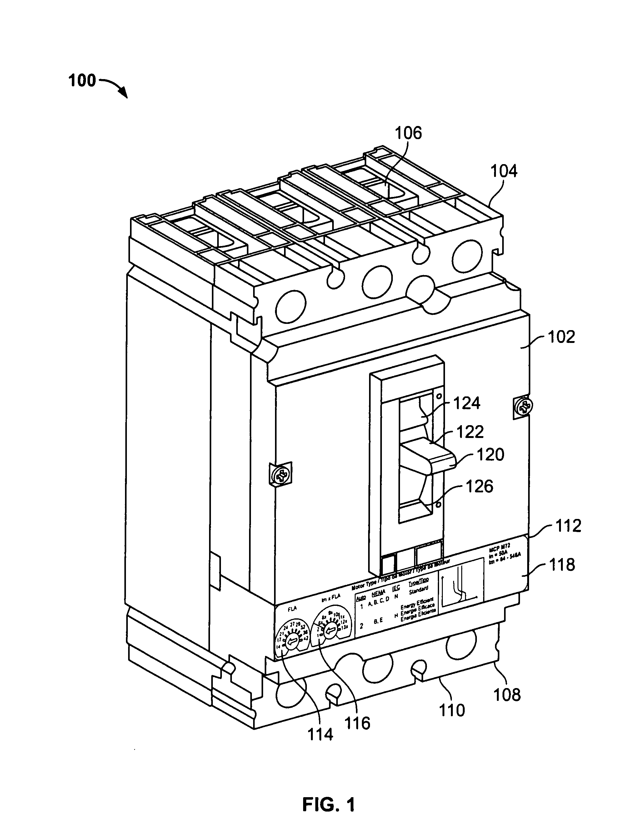
[0025]Turning now to FIG. 1, an electronic motor circuit protector 100 is shown. The motor circuit protector 100 includes a durable housing 102 including a line end 104 having line terminals 106 and a load end 108 having load lugs or terminals 110. The line terminals 106 allow the motor circuit protector 100 to be coupled to a power source and the load terminals 110 allow the motor circuit protector 100 to be coupled to an electrical load such as a motor as part of a motor control center (“MCC”). In this example the motor circuit protector 100 includes a three-phase circuit breaker with three poles, although the concepts described below may be used with circuit protectors with different numbers of poles, including a single pole.

[0026]The motor circuit protector 100 includes a control panel 112 with a full load ampere (“FLA”) dial 114 and an instantaneous trip point (“Im”) dial 116 which allows the user to configure the motor circuit protector 100 for a particular type of motor to be...


PUM


Abstract

A method and system to calibrate a motor circuit protection device is disclosed. An example method calibrates a signal chain of a circuit breaker. The signal chain includes a current transformer, a burden resistor, a stored energy circuit and a controller. The circuit breaker includes a memory coupled to the controller. A calibration instruction routine is written in a first location of the memory. A test current is injected in the circuit breaker signal chain. The test current peak of the test current in the circuit breaker signal chain is measured. Data indicative of the test current peak is stored in a second location of the memory. The test current peak data is read from the second location of the memory. The test current peak data is compared with nominal current data related to the signal chain remotely from the circuit breaker. A calibration factor is determined based on the comparison.

Description

RELATED APPLICATION[0001]The present application claims the benefit of U.S. Provisional Application Ser. No. 60 / 831,006, filed Jul. 14, 2006, titled: “Motor Circuit Protector,” and hereby incorporates that application by reference in its entirety.FIELD OF THE INVENTION[0002]The present invention relates generally to circuit breaker devices, and, in particular, to the calibration of components in an electronically controlled circuit breaker.BACKGROUND OF THE INVENTION[0003]As is well known, a circuit breaker is an automatically operated electro-mechanical device designed to protect a conductor from damage caused by an overload or a short circuit. Circuit breakers may also be utilized to protect loads. A circuit breaker may be tripped by an overload or short circuit, which causes an interruption of power to the load. A circuit breaker can be reset (either manually or automatically) to resume current flow to the load. One application of circuit breakers is to protect motors as part of ...

Claims


Application Information

Patent Timeline
Patent Type & Authority Applications(United States)
IPC IPC(8): G01R35/00G01R31/14G01M99/00
CPCH01H69/01
Inventor COLSCH, SUSAN JEAN WALKERDAVISON, WILLIAMDUNNE, DAVID JOSEPHMALO, KEVIN JOHNMEEHLEDER, STEVE M.MOFFITT, RYAN JAMESSTUDER, RICHARD ALLENSTUMME, GARY MICHAEL
Owner SQUARE D CO
Why Eureka
Try Eureka