Signal Separation Device, Signal Separation Method, Signal Separation Program and Recording Medium

a signal and signal separation technology, applied in the field of signal processing, can solve the problems of complex operations to accurately solve the permutation problem, errors in estimates, and inability to efficiently and simply use signal separation information obtained from signals observed by multiple sensors, etc., to achieve simple and efficient, accurate, and simple and efficient

Active Publication Date: 2008-09-04
NIPPON TELEGRAPH & TELEPHONE CORP
View PDF4 Cites 49 Cited by
  • Summary
  • Abstract
  • Description
  • Claims
  • Application Information

AI Technical Summary

Benefits of technology

[0050]As has been described, according to the present invention, information obtained from signals observed by multiple sensors can be used in a simple and efficient manner to perform signal separation.
[0051]For example, according to the first aspect of the present invention, the permutation problem can be solved accurately without needing to obtain information about the precise sensor positions beforehand or to perform complicated operations. According to the second aspect of the present invention, a target signal can be extracted from mixed signals which are a mixture of signals originated from multiple sources (even if N>M), without information about the direction of the target signal. According to the third aspect of the present invention, information obtained from all signals observed can be used in a simple and efficient manner to perform signal separation (even if N>M), without needing precise information about sensor positions.

Problems solved by technology

However, the conventional art described above had a problem that information obtained from signals observed by multiple sensors could not efficiently and simply be used for signal separation.
For example, a problem with the signal separation using independent component analysis is that it requires complicated operations to accurately solve the permutation problem.
Furthermore, the estimates have errors.
Another problem with the approach was that information about the positions of sensors had to be obtained beforehand because of the need for estimating information about the positions of signal sources.
This is disadvantageous when sensors are randomly disposed.
Even if sensors are regularly disposed, it is difficult to obtain precise positional information and therefore operations such as calibration must be performed in order to solve the permutation problem more accurately.
Accordingly, information about all sensors was not efficiently used, whereby the performance was limited.
Also this approach has a problem that precise information about the positions of sensors must be obtained beforehand.
This is disadvantageous when sensors are to be positioned randomly.
Even if sensors are regularly disposed, it is difficult to obtain precise positional information and therefore operations such as calibration must be performed for more accurate signal extraction.

Method used


Image

  • Signal Separation Device, Signal Separation Method, Signal Separation Program and Recording Medium
  • Signal Separation Device, Signal Separation Method, Signal Separation Program and Recording Medium
  • Signal Separation Device, Signal Separation Method, Signal Separation Program and Recording Medium

Examples


first embodiment

Example of the First Aspect of the Present Invention

[0105]The first embodiment of the present invention will be described.

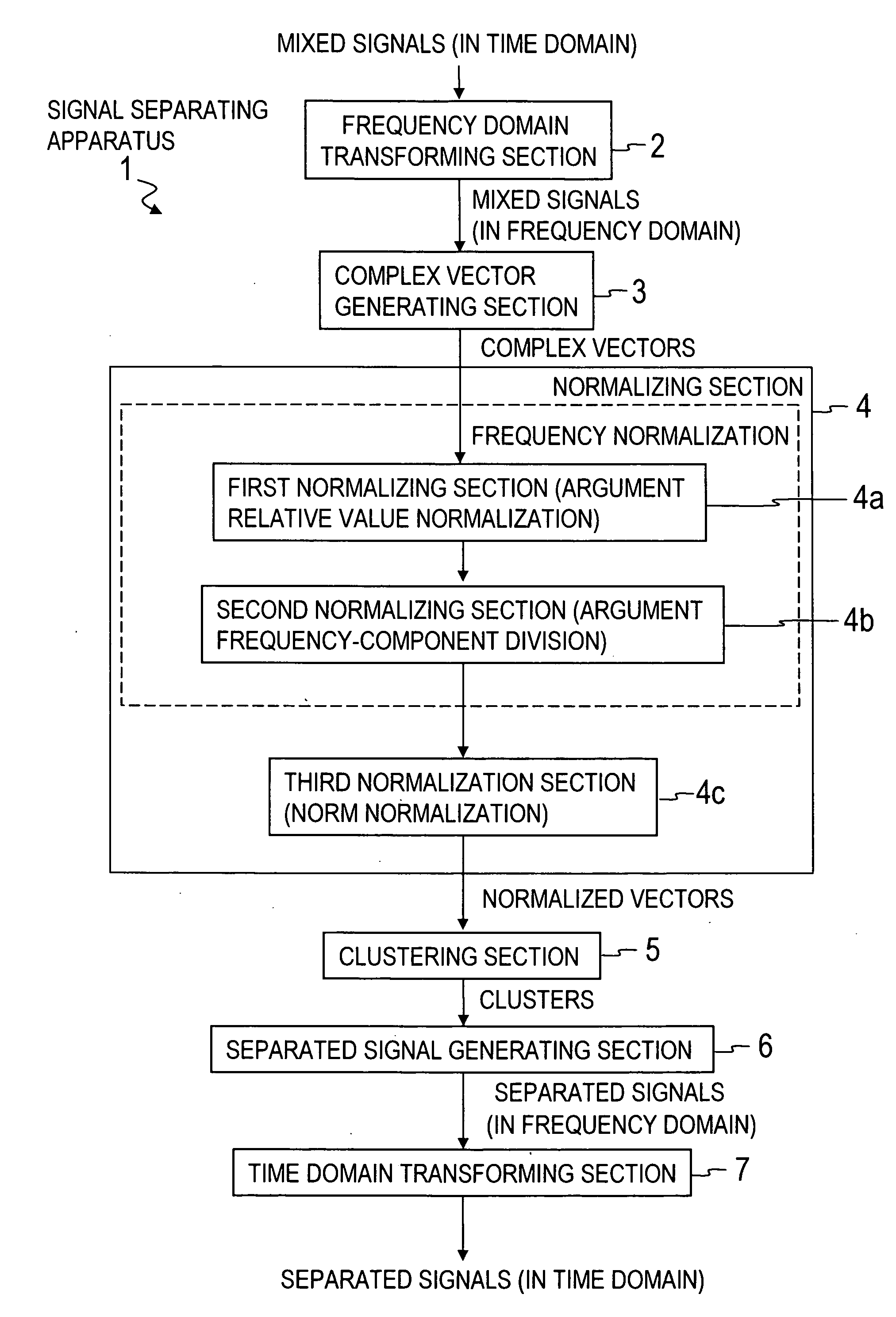
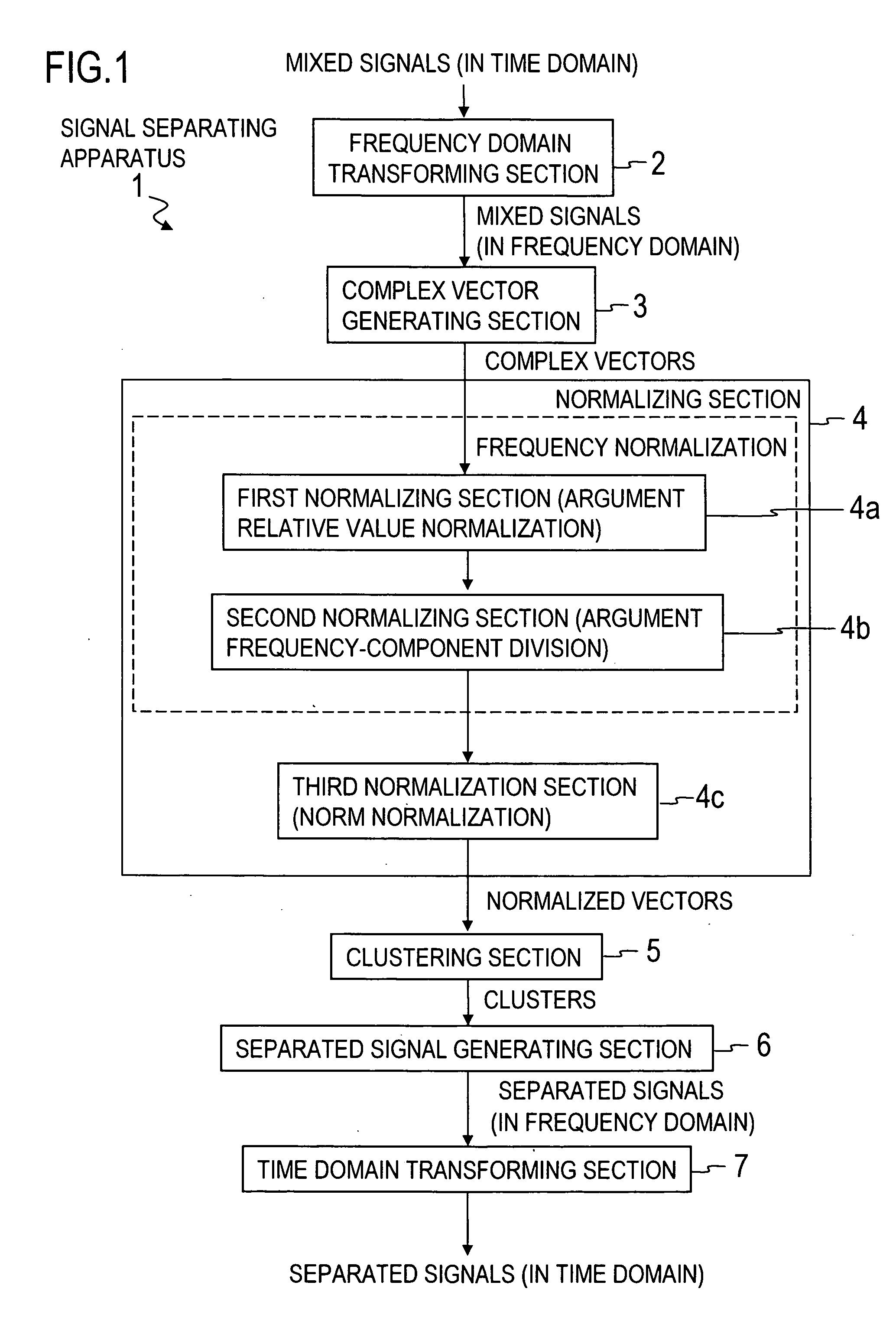
[0106]The first embodiment accurately solves the permutation problem in accordance with the principles described above, without needing to obtain precise information about sensor positions beforehand or to perform complicated operations. It should be noted that “basis vectors” described later correspond to the “complex vectors” mentioned above.

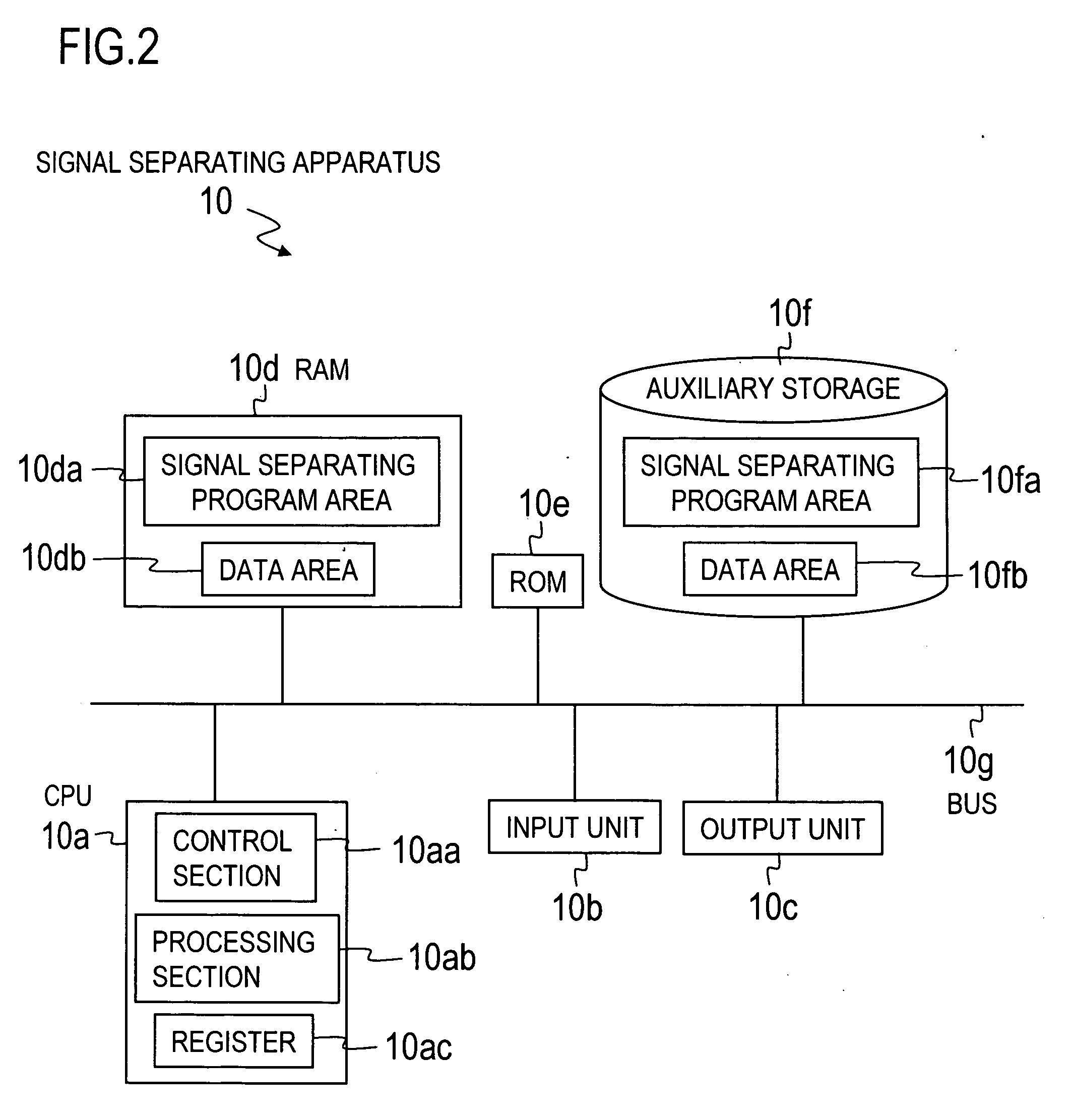
[0107]FIG. 2 is a block diagram showing a hardware configuration of a signal separating apparatus 10 according to the first embodiment.

[0108]As shown in FIG. 2, the signal separating apparatus 10 in this example includes a CPU (Central Processing Unit) 10a, an input unit 10b, an output unit 10c, an auxiliary storage device 10f, a RAM (Random Access Memory) 10d, a ROM (Read Only Memory) 10e, and a bus 10g.

[0109]The CPU 10a in this example includes a control section 10aa, a processing section 10ab, and a register 10ac and pe...

second embodiment

Example of the First Aspect of the Invention

[0159]The second embodiment of the present invention will be described below.

[0160]In the first embodiment, the permutation problem has been solved by using information obtained from basis vectors. In the second embodiment, the permutation problem is solved more accurately by combining this information with information about envelopes of separated signals as described in Japanese Patent Application Laid-Open No. 2004-145172 and H. Sawada, R. Mukai, S. Araki, S. Makino, “A Robust and Precise Method for Solving the Permutation Problem of Frequency-Domain Blind Source Separation,” IEEE Trans. Speech and Audio processing, Vol. 12, No. 5, pp. 530-538, September 2004 (hereinafter referred to as the “Reference literatures”). In these literatures, information about the directions of signal sources is used in stead of basis vectors.

[0161]The following description focuses on differences from the first embodiment and description of the same elements ...

third embodiment

Example of the Second Aspect of the Present Invention

[0195]The third embodiment of the present invention will be described below.

[0196]The third embodiment uses the principles described above to extract a target signal from mixed signals in which signals originated from multiple sources are mixed, without having information about the direction of the target signal.

[0197]Like the signal separating apparatus in the first embodiment, a signal separating apparatus of the present embodiment is configured by loading a signal separating program into a computer of well-known von Neumann-type. FIG. 16 is a block diagram illustrating a configuration of a signal separating apparatus 1001 according to the third embodiment.

[0198]As shown in FIG. 16, the signal separating apparatus 1001 has a memory 1100 including memory areas 1101-1114, a frequency domain transforming section 1120, a signal separating section 1130, a target signal selecting section 1140, a time-frequency masking section 1150 (wh...


PUM


Abstract

A frequency domain transforming section 2 transforms mixed signals observed by multiple sensors into mixed signals in the frequency domain, a complex vector generating section 3 generates a complex vector by using the frequency-domain mixed signals, a normalizing section 4 generates a normalized vector excluding frequency dependence of the complex vector, and a clustering section 5 clusters the normalized vectors to generate clusters. Then, a separated signal generating section 6 generates separated signals in the frequency domain by using information about the clusters and a time domain transforming section 7 transforms the separated signals in the frequency domain into separated signals in the time domain.

Description

TECHNICAL FIELD[0001]The present invention relates to the signal processing technical field and, in particular, to a technique for extracting a source signal from a mixture in which multiple source signals are mixed in a space.BACKGROUND ART[0002]A Beamformer (also called beamforming) is a widely-known conventional art of extracting a particular signal through use of multiple sensors and suppressing the other signals (for example see Non-patent literature 1). However, the beamformer requires information about the direction of a target signal and therefore has the drawback of being difficult to use in situations in which such information cannot be obtained (or cannot be estimated).[0003]One newer art is Blind Signal Separation (BSS) (for example see Non-patent literature 2). BSS is advantageous in that it does not require the information that the beamformer requires and is expected to find application in various situations. Signal separation using the BSS will be descried below.[0004...

Claims


Application Information

Patent Timeline
Patent Type & Authority Applications(United States)
IPC IPC(8): G06F17/14G10L21/0272G10L21/028
CPCG10L15/20G06K9/6245G10L2021/02165G10L21/0272G06F18/21347
Inventor SAWADA, HIROSHIARAKI, SHOKOMUKAI, RYOMAKINO, SHOJI
Owner NIPPON TELEGRAPH & TELEPHONE CORP
Why Eureka
Try Eureka