Heat plate construction and attachment for dismounting heat plate

a technology of heat plate and heat plate, which is applied in the direction of cooling/ventilation/heating modification, semiconductor/solid-state device details, semiconductor devices, etc., can solve the problem of not having the optimal design of the heat plate, and achieve the effect of convenient operation and reducing the probability of chip damag

Inactive Publication Date: 2008-09-11
INVENTEC CORP
View PDF4 Cites 5 Cited by
  • Summary
  • Abstract
  • Description
  • Claims
  • Application Information

AI Technical Summary

Benefits of technology

[0012]In the heat plate construction and the attachment for dismounting the heat plate according to the present invention, when the user dismounts a first locking element on the heat plate, the heat plate is loosed and becomes warped, the remaining end is still fixed on the circuit board under the stress effect of the locking element, but the buffer element is disposed between the fixing points of the heat plate and the heat source, so the other parts of the heat plate that are not loosed may press against the buffer element instead of the chip. Therefore, the buffer element can absorb the pressing force of the heat plate, so as to protect the chip from being damaged. In addition, the attachment with the buffer element also can be used to dismount the heat plate, and the force for the heat plate to press against the chip is also absorbed. Besides being convenient for the user to operate, it also reduces the probability for damaging the chip when the heat plate is removed.

Problems solved by technology

In view of the above conventional art, although the base platform has been disposed with pads, the pads are not disposed on the region of the base platform between the fixing hole and the chip, such that the base platform at this part may directly press against the central processing unit (CPU) chip, which cannot fully protect the chip, and thus, it is not the optimal design of the heat plate.

Method used


Image

  • Heat plate construction and attachment for dismounting heat plate
  • Heat plate construction and attachment for dismounting heat plate
  • Heat plate construction and attachment for dismounting heat plate

Examples


Embodiment Construction

[0027]In order to make a further understanding of the objectives, construction, features, and functions of the present invention, the detailed description is given below through the following embodiments.

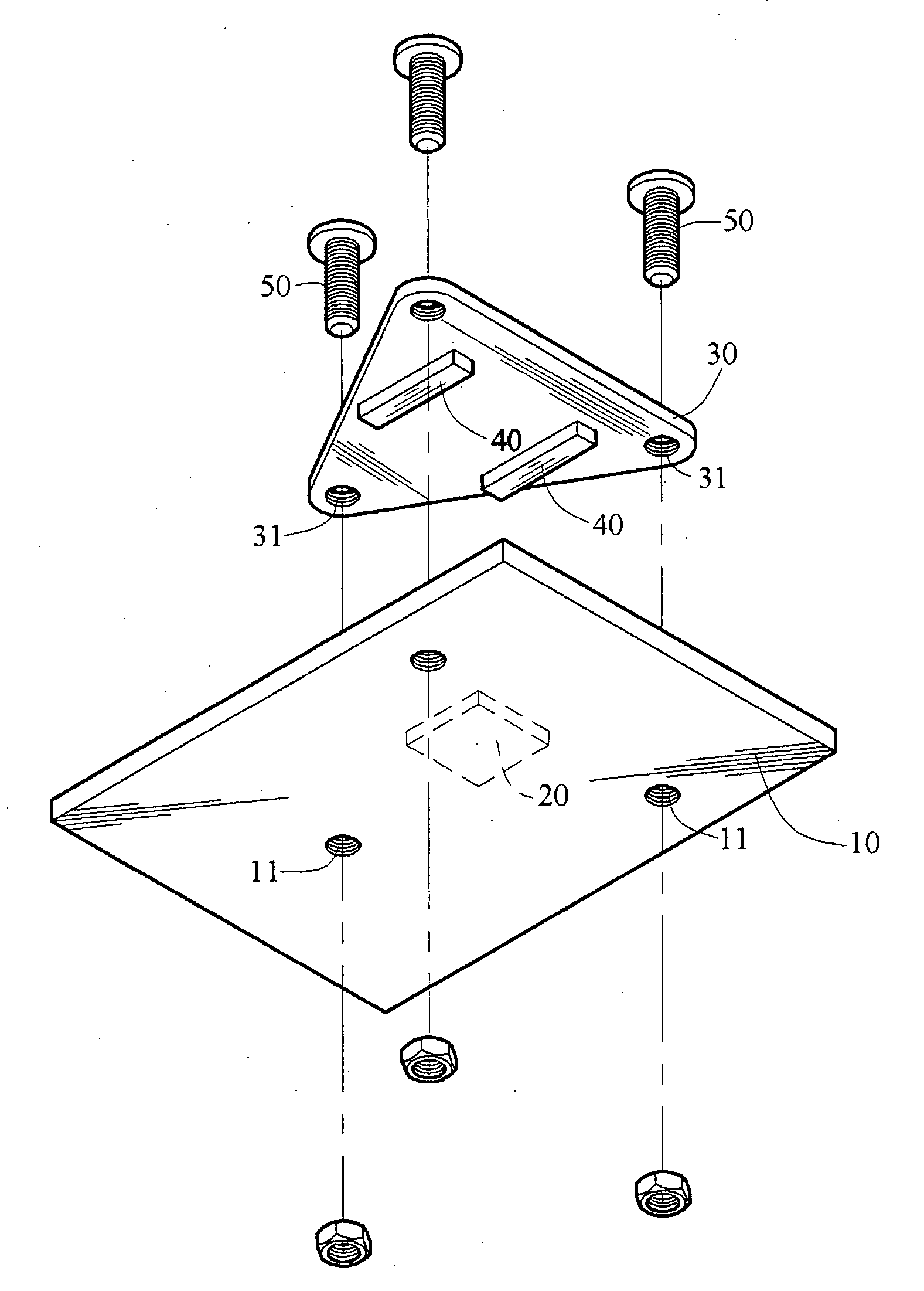
[0028]In the heat plate construction and the attachment for dismounting the heat plate according to the present invention, the heat plate contacts with the heat source. The heat source may be a CPU chip, a north bridge chip, a south bridge chip, and the like, but it is not limited to the CPU chip, the north bridge chip, and the south bridge chip, and for example, the integrated circuits (ICs) chip that generates heats also can be applied to the technique provided by the present invention. In the following detailed description of the present invention, the CPU chip is set as an example for an application embodiment of the present invention.

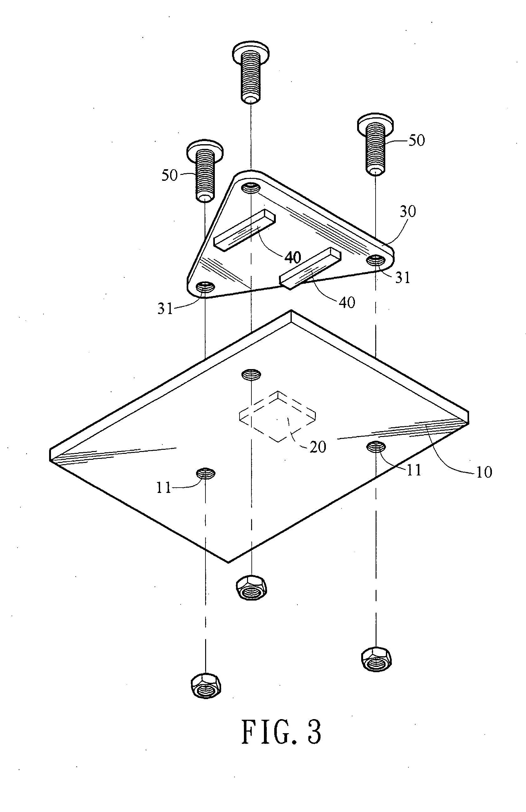
[0029]Referring to FIGS. 3, 4A, and 4B, the heat plate construction in this embodiment of the present invention is fixed on the circuit board 10 a...


PUM


Abstract

A heat plate construction is provided, which is applicable for being fixed on a circuit board and contacting with a chip to perform a heat exchange. The heat plate construction includes a heat plate body and at least one buffer element. The heat plate body has a plurality of fixing points fixed on the circuit board and located outside the contacting region between the heat plate body and the chip. The buffer element is disposed outside the contacting region between the heat plate body and the chip, and the height of the buffer element is equal to a distance between the heat plate body and the circuit board, such that when the heat plate is dismounted, the buffer element relieves a force for the heat plate to press against the chip, so as to protect the chip from being damaged.

Description

BACKGROUND OF THE INVENTION[0001]1. Field of Invention[0002]The present invention relates to a heat plate construction. More particularly, the present invention relates to a heat plate construction, which is capable of providing a balanced buffer force.[0003]2. Related Art[0004]Electronic elements in computer equipments, such as a central processing unit (CPU) chip and a power integrated circuit (IC), generate heats during the operation, and the working temperature is increased accordingly. Since the working temperature greatly affects whether the computer equipment is crashed or not, in order to reduce the working temperature of the heating electronic element and to maintain the effective operation, various heatsinks are designed through a heatsink design. For example, a heatsink module is pressed on the CPU chip on a circuit board, and locked on the circuit board, such that the heatsink module closely contacts with the CPU chip, and thereby achieving a heat dissipation effect.[000...

Claims


Application Information

Patent Timeline
Patent Type & Authority Applications(United States)
IPC IPC(8): H05K7/20
CPCH01L23/36H01L23/3672H01L23/4006H01L2023/4062H01L2924/0002H01L2023/4087H01L2924/00
Inventor WANG, FENG-KUCHEN, HUA-FONG
Owner INVENTEC CORP
Why Eureka
Try Eureka