Monolithic Enclosed Cable Carrier

a cable carrier, monolithic technology, applied in the direction of cables, insulated conductors, cables, etc., can solve the problems of difficult handling in long sections, difficult manufacturing, assembly and disassembly, etc., to reduce the size of the space, easy to load, and pliable and soft material

Inactive Publication Date: 2008-09-11
DYNATECT MFG
View PDF12 Cites 29 Cited by
  • Summary
  • Abstract
  • Description
  • Claims
  • Application Information

AI Technical Summary

Benefits of technology

[0010]Preferably, at least the stiffer one of the sides has a laterally convex or arched profile and may be of a relatively hard and resilient material, at least in part, so as to help support the cable carrier in a straight position, but allow bending of the cable carrier around the normal U-bend, typically 180°, as is normal in cable carrier installations. When going around the U-bend of the cable carrier, this side tends to flatten out laterally, i.e., become less arched in the lateral direction, which tends to reduce the size of the space between the first and second sides. The second side should be made of a relatively more pliable and soft material which permits it to go around the U-bend of the cable carrier without excessively closing off the space between the first and second sides and to maintain that space around the enclosed cables and hoses.
[0011]The first and second sides can be integrally made of materials with different characteristics by a co-molding process, such as co-extrusion The first side can be made of a relatively hard and stiff material with the second side made of a softer and more flexible material, with the first and second sides joined at the first edge, or at both edges. The second edge of the second side and the second edge of the first side, or one of the sides, can be formed to have a longitudinally running tongue and groove type releasable “zipper” coupling. The softer material of the one side also forms a living hinge that allows the cable carrier to be easily loaded to permit loading energy carriers such as hoses and cables into it.

Problems solved by technology

Carriers with individual or continuous cross-links or covers fixed to the side plates require many parts, making manufacture, assembly, and disassembly more difficult.
Sheet metal band covers, whether flat or arched laterally, can have sharp edges which can abrade the cables and hoses, require an open joint at the sides, and can be difficult to handle in long sections.

Method used


Image

  • Monolithic Enclosed Cable Carrier
  • Monolithic Enclosed Cable Carrier
  • Monolithic Enclosed Cable Carrier

Examples


Embodiment Construction

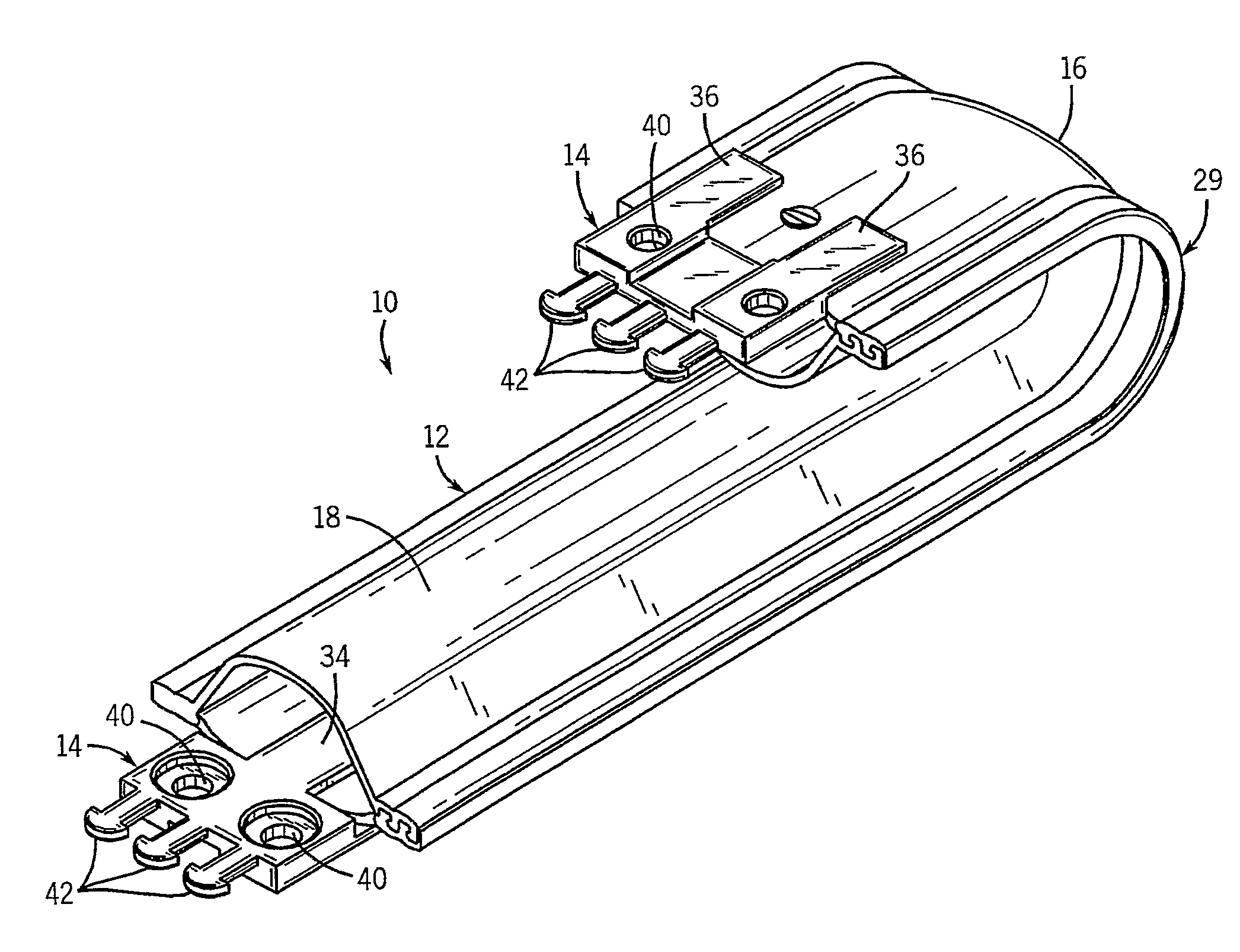
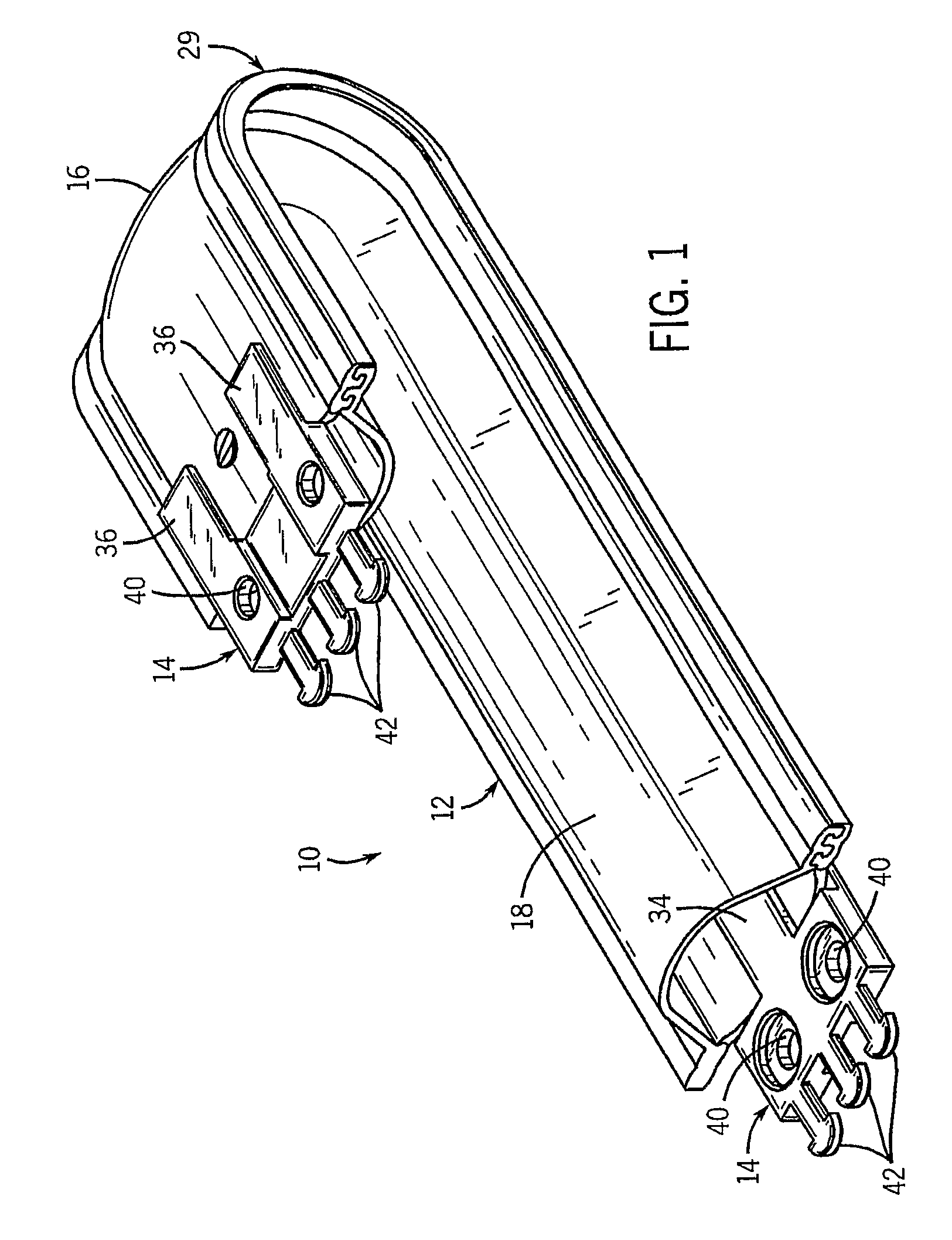
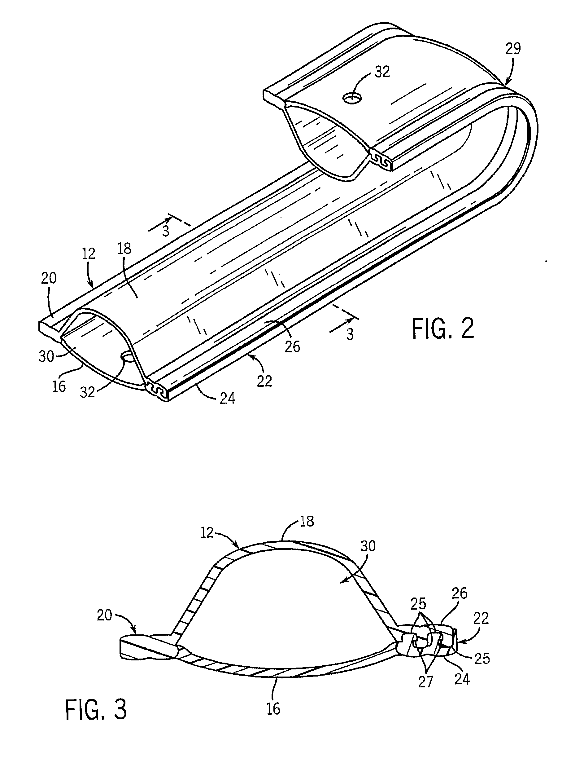
[0020]FIG. 1 illustrates a cable carrier 10 of the invention including a carrier body 12 and two end connectors 14 attached to the body 12. Referring to FIGS. 2 and 3, the body 12 is formed in one piece, having a first side 16, a second side 18, a first edge 20 that is integral with the first and second sides 16 and 18, and a second edge 22 that is formed of a releasable connection between the free edge 24 of the first side 16 and the free edge 26 of the second side 18. Each of the free edges 24 and 26 form tongue and groove interlocking structures 25 having undercut shoulders 27 that interlock for the full length of the body 12 to provide a seal for the full length against dust, dirt, and moisture entry to the interior space 30 that is between the first and second sides 16 and 18.

[0021]In the preferred form as illustrated, the edge 22 is a zip lock-type seal, but any structure which is releasable and when engaged closes the interior 30 of the body 12 could be used. To load cables a...


PUM

PropertyMeasurementUnit
thickaaaaaaaaaa
thicknessaaaaaaaaaa
thickaaaaaaaaaa

Abstract

A cable carrier (10) has top (18) and bottom (16) longitudinally continuous sides, with one side (18) more flexible and the opposite side (16) less flexible. The sides are made of continuous sheets of material to define a closed tubular shape in which energy carriers can be housed and supported. The sheets may be integral, or have integral parts, and can be extruded. The carrier may be longitudinally openable with a zipper structure (125) to permit loading of energy carriers.

Description

CROSS-REFERENCE TO RELATED APPLICATION[0001]This claims the benefit of U.S. Provisional Patent Application No. 60 / 538,809 filed Jan. 23, 2004.STATEMENT CONCERNING FEDERALLY SPONSORED RESEARCH OR DEVELOPMENT[0002]Not applicable.FIELD OF THE INVENTION[0003]This invention relates to cable carriers, and in particular to self-supporting cable carriers.BACKGROUND OF THE INVENTION[0004]Cable carriers are well known in the industry and, although called cable carriers, carry flexible hoses, cables, wires, or any elongated energy transmission conduits that can bend around the U-bend of the cable carrier as it moves back and forth. As is well known, one end of the cable carrier is fixed, and the other end of the cable carrier is attached to a movable head of a machine, for example of a machine tool, with a U-bend of the cable carrier in between an upper self supporting straight run and a lower straight run of the carrier so that the relative length of the two runs varies as the movable end of ...

Claims


Application Information

Patent Timeline
Patent Type & Authority Applications(United States)
IPC IPC(8): F16L3/08H02G3/04F16L3/26H02G9/06H02G11/00
CPCF16L3/26H02G11/00H02G9/065Y10S59/90
Inventor O'ROURKE, JAMES D.O'BRIEN, JAY R.ZANOLLA, MARK A.
Owner DYNATECT MFG
Why Eureka
Try Eureka