Bandwidth wireline data transmission system and method

Active Publication Date: 2008-09-11
BAKER HUGHES INC
View PDF3 Cites 14 Cited by
  • Summary
  • Abstract
  • Description
  • Claims
  • Application Information

AI Technical Summary

Benefits of technology

[0019]In aspects, the present disclosure provides a suspended well logging system for use in logging a well. The system may include a plurality of twisted pairs of signal conductors; a conductive armor surrounding the plurality of twisted pairs of signal conductors; a plurality of channels formed using the plurality of twisted pairs of signal conductors, wherein at least one channel is formed using at least one pair of twisted signal conductors and the armor. A wellbore logging tool may be operatively coupled to at least one of the plurality of channels. The well logging system may include a power supply that is operatively coupled to at least one channel of the plurality of channels. In embodiments, the well logging system may include a plurality of power supplies, each of which is operatively coupled a separate channel of the plurality of channels. The plurality of power supplies may includes one or more AC power sources and/or one or more DC power sources.
[0020]In embodiments, the well log

Problems solved by technology

However, the wireline transmission medium does cause a problem when the transmission is over a relatively long length or as the data rate increases.
That is, the detection and distinguishing of the two voltage levels associated with the digital signal is impaired by distortions caused by the medium.
Today, while the wells become deeper, the measuring devices have also become more complex.
The cables have become more complex i.e., they have added conductors, and the band pass requirements for the conductors have been increased.
Still, the cables used today are unable to provide bandwidth in deep wells matching the transmission capabilities of the instrumentation.
Such arrays as described in the '133 and '751 patents are not wireline systems and are unsuitable for self-supporting wireline logging in the drilling phase due to the need quickly insert the wireline data logger into a well borehole, take measurements and then remove the wireline all during a tripping cycle of the drill string.
One problem with implementing twisted pair conductors in a self-supporting wireline is stress induced at each twist crossing point causes conductor deformation or failure at the crossing point when high tensile loads are supplied.
Therefore, prior wireline systems are typically designed to a standard wireline cable using single conductors or systems are designed with complicated clamping measures to secure and support the cable during use.
At this time, the well logging community has not taken advantage of the state of the art encoding methods.
The primary driver being that the cables in current use cannot provide the bandwidth necessary to utilize these encoding methods efficiently.

Method used


Image

  • Bandwidth wireline data transmission system and method
  • Bandwidth wireline data transmission system and method
  • Bandwidth wireline data transmission system and method

Examples


Embodiment Construction

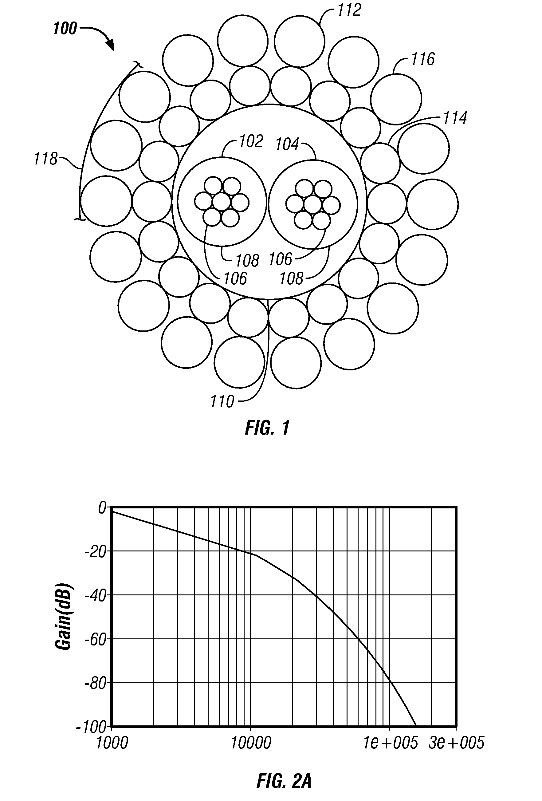
[0031]FIG. 1 is a cross section view of a suspended well logging cable according to an embodiment of the present disclosure. The term suspend or suspended is used as those skilled in the art of wireline would understand, which understanding is to support the wireline cable at an upper point while allowing the remainder of the structure to hang substantially free on all sides so as not to sink or fall into the well borehole. A suspended wireline logging cable 100 according to one embodiment includes a twisted pair of insulated signal conductors 102 and 104 helically twisted together and positioned along a central axis of the cable. Each of the insulated conductors 102 and 104 comprises a group of electrically conductive stranded wires 106 encased by a tightly fitted, tubular sheath of insulating material 108. The stranded wires may be copper or any other suitable metallic material, and the insulating material 108 is preferably an extrudable plastic, which maximizes electrical insulat...


PUM


Abstract

A suspended well logging device for use in a wellbore drilled in an earthen formation may include a cable configured to be conveyed into the wellbore; a single twisted pair of conductors positioned in the cable; and a conductive armor surrounding the single twisted pair of conductors. In embodiments, the device may further include a first channel formed using the single twisted pair of conductors; a second channel formed using the single twisted pair of conductors and the armor; and a wellbore logging tool coupled to an end of the cable.

Description

CROSS-REFERENCE TO RELATED APPLICATIONS[0001]This application is a continuation-in-part of U.S. application Ser. No.11 / 611,646 filed on Dec.15, 2006, which is a continuation of U.S. application Ser. No. 11 / 086,944 filed Mar. 22, 2005, now abandoned, which is a continuation-in part of U.S. application Ser. No. 09 / 586,130 filed on Jun. 2, 2000, now abandoned, which application takes priority from U.S. Provisional Application No. 60 / 193,098 titled “Improved Bandwidth Wireline Data Transmission System and Method” filed on Mar. 30, 2000, the entire specification of each application being hereby incorporated herein by reference.BACKGROUND OF THE DISCLOSURE[0002]1. Field of the Disclosure[0003]This disclosure pertains to data communications and particularly to data communications on a wireline such as one employed in an oil or gas well borehole application.[0004]2. Description of the Prior Art[0005]It is common in an oil or gas well borehole application to transmit and receive electrical d...

Claims


Application Information

Patent Timeline
IPC IPC(8): G01V3/00
CPCG01V1/52
Inventor VISWANATHAN, RAMANGOLD, RANDY
Owner BAKER HUGHES INC
Why Eureka
Try Eureka