Zero-lag image response to pilot head mounted display control

a technology of display control and gimbal, which is applied in the field can solve the problems of limiting the ability to provide a remote camera to a pilot, affecting the response speed of gimbal controlled video imagery, and becoming more problematic, so as to achieve the effect of gaining a great deal of response speed and electronic stabilization capability, and extreme electronic complexity

Active Publication Date: 2008-09-11
LOCKHEED MARTIN CORP
View PDF4 Cites 25 Cited by
  • Summary
  • Abstract
  • Description
  • Claims
  • Application Information

AI Technical Summary

Benefits of technology

[0005]Accordingly, embodiments of the present invention are directed to provide a single high resolution camera (focal plane array) or a grouping of relatively limited number (e.g., two to four) lower resolution cameras to provide an “active” FOV that is larger than what is displayed on a pilot's head mounted display. More particularly, the inner FOV would move within the camera's array in a way similar to that of the staring array concept except on a smaller scale. Further, by hybridizing an electronic inner gimbal with a mechanical servo system, it is possible to gain much of the response speed and electronic stabilization capability of the staring array without its extreme electronic complexity.

Problems solved by technology

Gimbal controlled video imagery inherently suffers a lag in response due to the required mechanical movement and re-stabilization of line of sight (LOS) of the device.
Although, this system may instantaneously follow a pilot's head movements to provide a high level of situational awareness, this technique can be problematic because the required FOV requires a relatively large number of detector / optic sets (e.g., 18) in addition to associated costly processing requirements.
Although this system may be operable in the pitch and yaw directions, it becomes more problematic when this system utilizes a method of altering the clocking sequence to have access to the timing signal of the detector.
Thus, this system limits the ability to provide a remote camera to a pilot using a head mounted display.
This is achieved with a Staring Array configuration but such configurations are impractical to implement for high resolution imaging systems.

Method used


Image

  • Zero-lag image response to pilot head mounted display control
  • Zero-lag image response to pilot head mounted display control
  • Zero-lag image response to pilot head mounted display control

Examples


Embodiment Construction

[0018]The following detailed description of the embodiments of the invention refers to the accompanying drawings. The following detailed description does not limit the invention. Instead, the scope of the invention is defined by the appended claims and equivalents thereof.

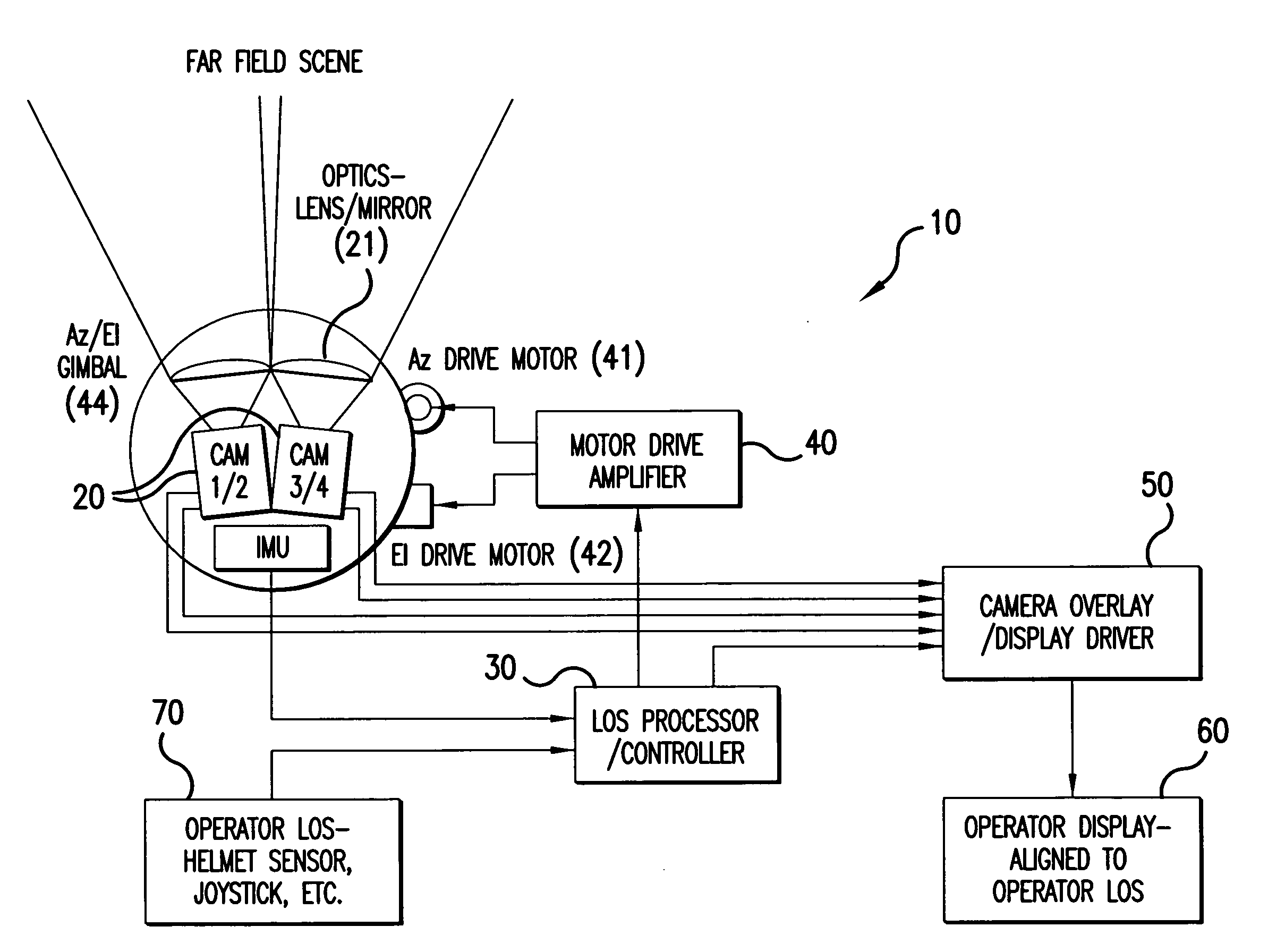
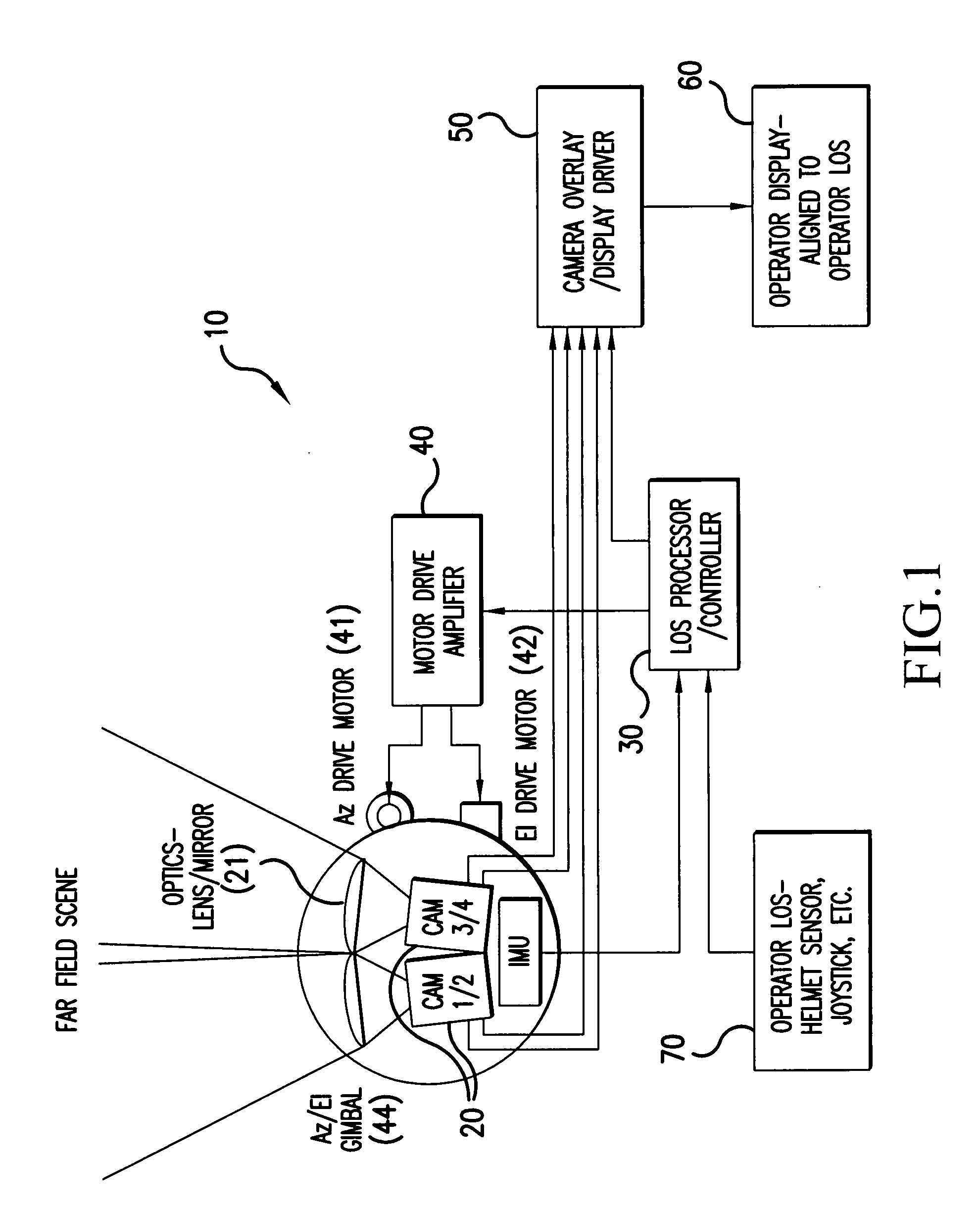
[0019]FIG. 1 depicts a system 10 for tracking a LOS of a target and providing substantially zero-lag image response to a pilot using a head mounted display consistent with an embodiment of the invention. The system 10 includes an electronic inner gimbal unit 20, optic lens / mirror 21, a LOS processor / controller 30, a motor drive amplifier 40, an azimuth drive motor 41, an elevation drive motor 42, an inertial measurement unit (IMU) 43, a camera overlay / display driver 50, an operator display unit 60, and an operator LOS unit 70.

[0020]In accordance with an exemplary embodiment of the present invention, one end of the electronic gimbal unit 20 is connected with the camera overlay / display driver 50 and the other end of ...


PUM


Abstract

A method and a system for tracking a line-of-sight (LOS) and providing zero-lag image response to a display is disclosed. The method according to one embodiment receives image data having a filed of view (FOV) that is larger than what is displayed on the display using an initial LOS, combines the received image data to create a region of interest (ROI) image, detects a change in the LOS, creates a new ROI image using the received image data to correspond to the changed LOS, and displays the new ROI image to the display.

Description

BACKGROUND OF THE INVENTION[0001]Embodiments of the present invention generally relate to gimbal controlled video imagery, and more specifically, incorporating an electronic inner gimbal that works in conjunction with a mechanical outer gimbal of a video imagery device to provide substantially zero-lag image response to a display of the device.[0002]Substantially zero-lag image response is especially helpful in close-in combat situations requiring fast movements and situational awareness. Gimbal controlled video imagery inherently suffers a lag in response due to the required mechanical movement and re-stabilization of line of sight (LOS) of the device.[0003]In the past, various approaches have been tried to improve the ability to provide quick response to a head mounted display (HMD). One approach used by TADS / PNVS includes providing a floating mechanical inner gimbal that improves the response and stabilization of LOS of a Target Acquisition Designation Sight (TADS) system or a Pi...

Claims


Application Information

Patent Timeline
Patent Type & Authority Applications(United States)
IPC IPC(8): G09G5/00
CPCG02B27/017G02B2027/0187G02B2027/014G02B2027/0138
Inventor LIPSCOMB, DERREL
Owner LOCKHEED MARTIN CORP
Why Eureka
Try Eureka