Organic electroluminescence display

Inactive Publication Date: 2008-09-11
SONY CORP
View PDF11 Cites 16 Cited by
  • Summary
  • Abstract
  • Description
  • Claims
  • Application Information

AI Technical Summary

Benefits of technology

[0043]As transistors included in the drive circuit, an n-channel thin film transistor (TFT) is available. However, depending on the case, it is also possible to employ a p-channel thin film transistor for a light-emission control transistor, for example. Alternatively, it is also possible that the transistors be formed of field effect transistors (e.g. MOS transistors) formed on a silicon semiconductor substrate. The auxiliary capacitor can be formed from one electrode, the other electrode, and a dielectric layer (insulating layer) interposed between these electrodes. The capacitor can also be formed from one electrode, the other electrode, and a dielectric layer (insulating layer) interposed between these electrodes. The transistors and the capacitor of the drive circuit and the auxiliary capacitor are formed in a certain plane (for example, formed on a support body). The light-emitting part is formed above the transistors and the capacitor of the drive circuit and the auxiliary capacitor with the intermediary of an interlayer insulating layer, for example. The other source/drain region of the drive transistor is connected via e.g. a contact hole to the anode electrode of the light-emitting part. Furthermore, one electrode of the auxiliary capacitor is also connected to the other source/drain region of the drive transistor.
[0044]In the present invention, the

Problems solved by technology

Consequently, the lower the capacitance cEL of the parasitic capacitor CEL of the light-emitting part ELP is, the shorter the execution time of the mobility correction processing needs to be, and hence, the control of the time of the mobility correction processing is more difficult.
Due to this current increase, the difference in the capacitance of the parasitic capacitor among three sub-pixels (e.g.

Method used


Image

  • Organic electroluminescence display
  • Organic electroluminescence display
  • Organic electroluminescence display

Examples


Example

First Embodiment

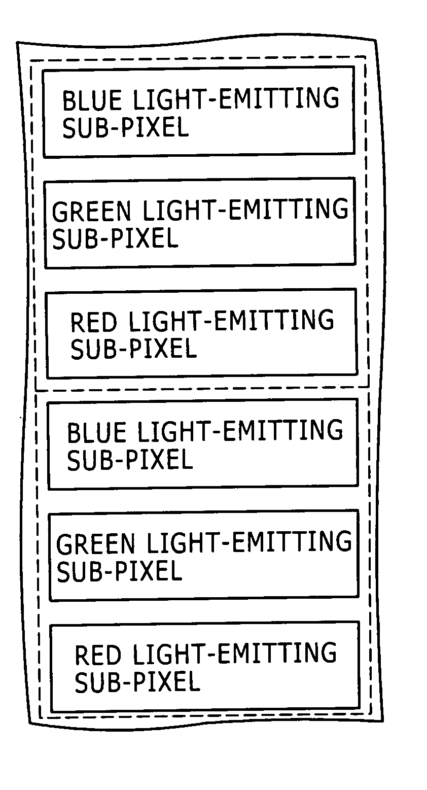
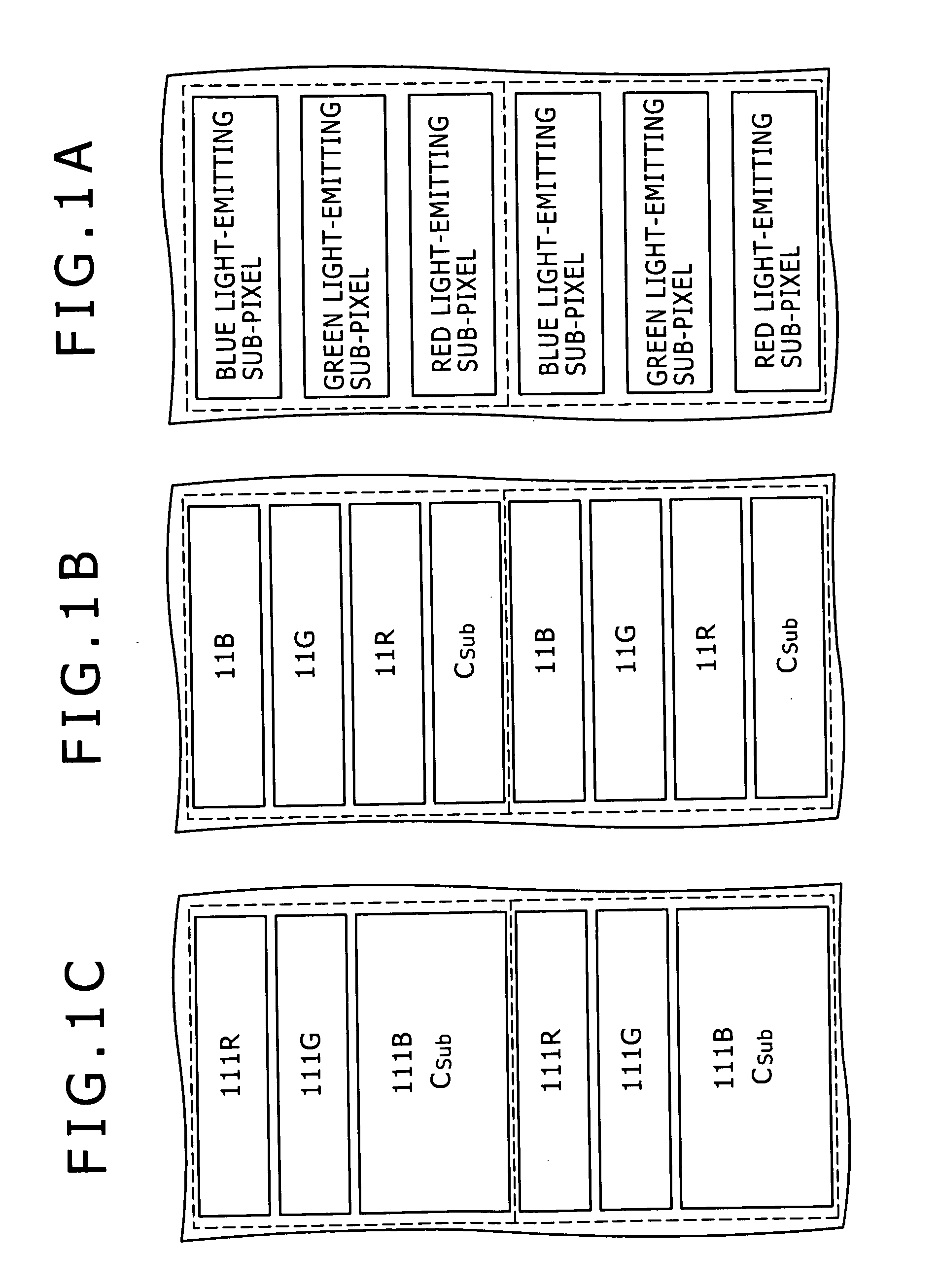
[0071]A first embodiment of the present invention relates to an organic EL display according to the first mode of the present invention. FIG. 1A is a conceptual diagram (plan view) of a plane occupied by one pixel. FIG. 1B is a conceptual diagram (plan view) of a plane occupied by three drive circuits and one auxiliary capacitor CSub. One pixel is surrounded by a dashed line, and each of the sub-pixels, drive circuits, and auxiliary capacitors is surrounded by a full line. Two pixels are indicated in each of FIGS. 1A, 1B, and 1C.

Example

[0072]Organic EL displays of the first embodiment and a second embodiment of the present invention, which will be described later, include plural pixels. Furthermore, each pixel is composed of plural sub-pixels (in the first embodiment and the second embodiment to be described later, three sub-pixels of a red light-emitting sub-pixel, a green light-emitting sub-pixel, and a blue light-emitting sub-pixel). Each of the sub-pixels is formed of an organic electroluminescence element (organic EL element 10) that has a structure arising from stacking a drive circuit 11 and an organic electroluminescence light-emitting part (light-emitting part ELP) connected to this drive circuit 11. The drive circuit of a red light-emitting sub-pixel is indicated by reference numeral 11R, the drive circuit of a green light-emitting sub-pixel is indicated by reference numeral 11G, and the drive circuit of a blue light-emitting sub-pixel is indicated by reference numeral 11B.

[0073]In the organic EL display...


PUM


Abstract

The present invention is to provide an organic electroluminescence display including a plurality of pixels, each pixel being composed of a plurality of sub-pixels, each of the sub-pixels having: an organic electroluminescence element configured to have a structure arising from stacking a drive circuit and an organic electroluminescence light-emitting part connected to the drive circuit; wherein to the drive circuit of one sub-pixel of the plurality of sub-pixels included in one pixel, an auxiliary capacitor connected in parallel to the organic electroluminescence light-emitting part of the drive circuit is connected, and the auxiliary capacitor is provided in the same plane as that of the drive circuit.

Description

CROSS REFERENCES TO RELATED APPLICATIONS[0001]The present invention contains subject matter related to Japanese Patent Application JP 2007-058885 filed in the Japan Patent Office on Mar. 8, 2007, the entire contents of which being incorporated herein by reference.BACKGROUND OF THE INVENTION[0002]1. Field of the Invention[0003]The present invention relates to an organic electroluminescence display.[0004]2. Description of the Related Art[0005]In an organic electroluminescence display (hereinafter, abbreviated as an organic EL display) employing an organic electroluminescence element (hereinafter, abbreviated as an organic EL element) as its light-emitting element, the luminance of the organic EL element is controlled based on the current that flows through the organic EL element. Similar to a liquid crystal display, a simple-matrix system and an active-matrix system are known as the driving system of the organic EL display. The active-matrix system has various advantages that it can p...

Claims


Application Information

Patent Timeline
IPC IPC(8): G09G3/30
CPCG09G3/325G09G2300/0814G09G2300/0819G09G2320/043G09G2300/0876G09G2320/0233G09G2300/0861G09G3/20G09G3/30G09G3/32H05B33/12
Inventor YAMAMOTO, TETSUROUCHINO, KATSUHIDE
Owner SONY CORP
Why Eureka
Try Eureka