
Inkjet printing partially imaged panels with superimposed layers

Inactive Publication Date: 2008-09-11
CONTRA VISION
View PDF10 Cites 43 Cited by
  • Summary
  • Abstract
  • Description
  • Claims
  • Application Information

AI Technical Summary

Benefits of technology

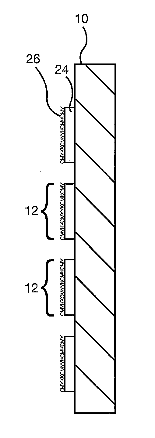
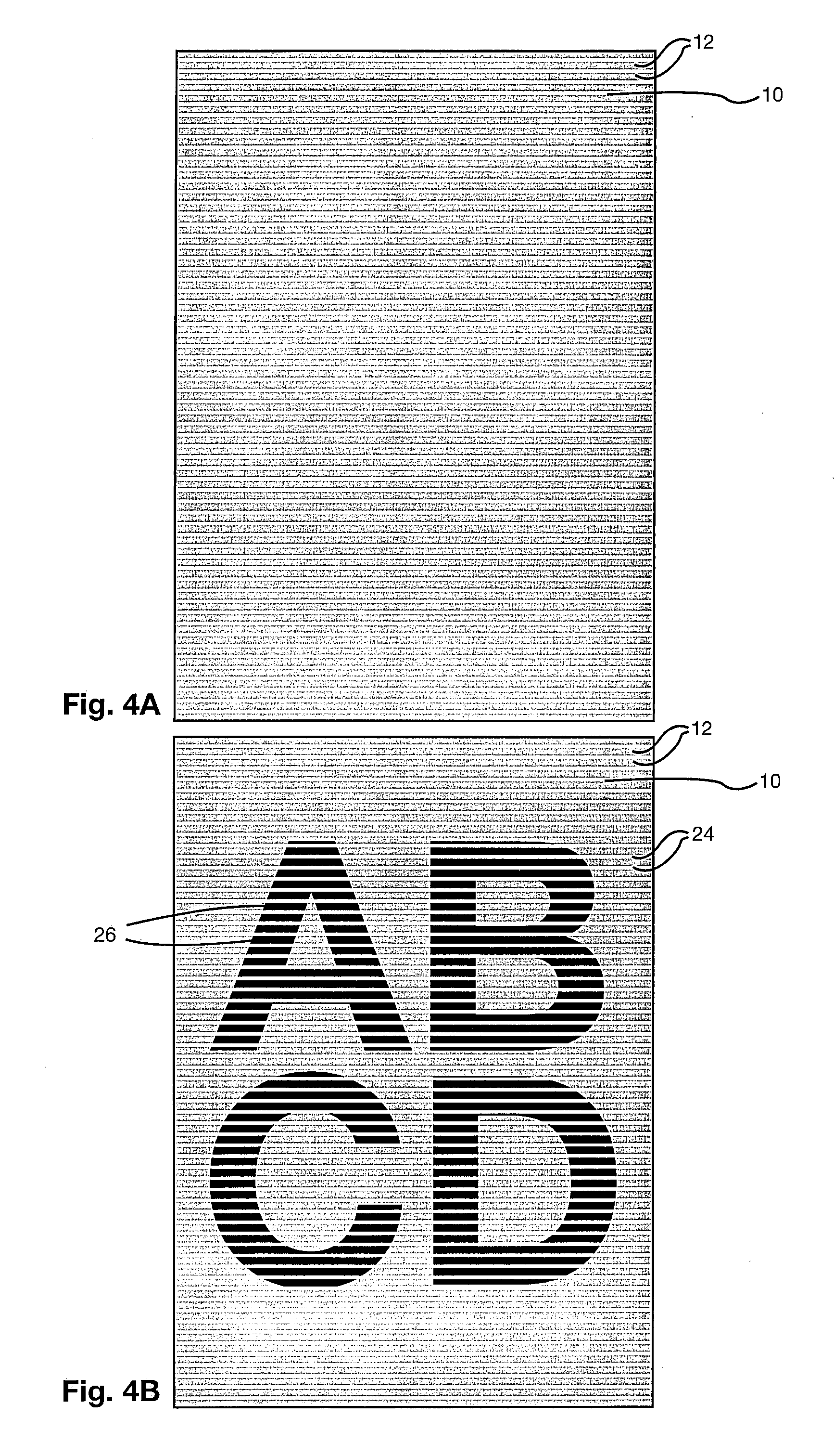
[0027]The term “print pattern” as used herein is intended to mean the geometric pattern within which the plurality of ink layers are located and all the edges of the print pattern are coincident with an edge of at least one of the plurality of ink layers. The print pattern comprises a plurality of connected and/or unconnected print pattern elements. The print pattern subdivides the panel into a plurality of discrete printed areas and/or a plurality of discrete unprinted areas. The print pattern may be in many forms, for example it may be a regular geometric element in a regular layout, such as a uniform pattern of hexagons or circular dots, a regular geometric element in an irregular layout, a free form element in a regular layout, a free form element in an irregular layout or a combination of regular and free-form elements in regular and/or irregular layouts. Instead of a number of discrete (separate) elements with an interconnected unprinted zone, the print pattern can be a pattern of discrete print pattern elements and discrete unprinted areas, such as a pattern of lines. Alternatively, the print pattern may be formed by interconnected print pattern elements with discrete unprinted areas, such as net, grid or mesh pattern. The print pattern can, if desired, be

Problems solved by technology

It also describes four inkjet printer movement mechanisms 1-4 and, for each, the relative movement of a printhead array in relation to a substrate sheet but does not disclose the movement mechanism of inkjet cylindrical printers with hardly discernible movement of a printhead array and does not disclose the use of white ink with inkjet cylindrical printers.
It is impossible with such machines to accurately register one layer of ink to another layer previously applied and cured in a separate curing process remote from the cylinder.
There are known problems with inkjet printing white ink, and the more “opaque” it is desired to make the printed white ink (having a relatively high Transmission Optical Density or TOD), the more these difficulties are exacerbated.
While a range of other types of digital UV inkjet printing machines have been introduced onto the market with a white ink option, none have white ink delivered to printheads which move relatively slowly compared to the speed of movement of the substrate, that is in the secondary direction of relative movement of the printheads to the substrate.

Method used


Image

  • Inkjet printing partially imaged panels with superimposed layers
  • Inkjet printing partially imaged panels with superimposed layers
  • Inkjet printing partially imaged panels with superimposed layers

Examples


first embodiment

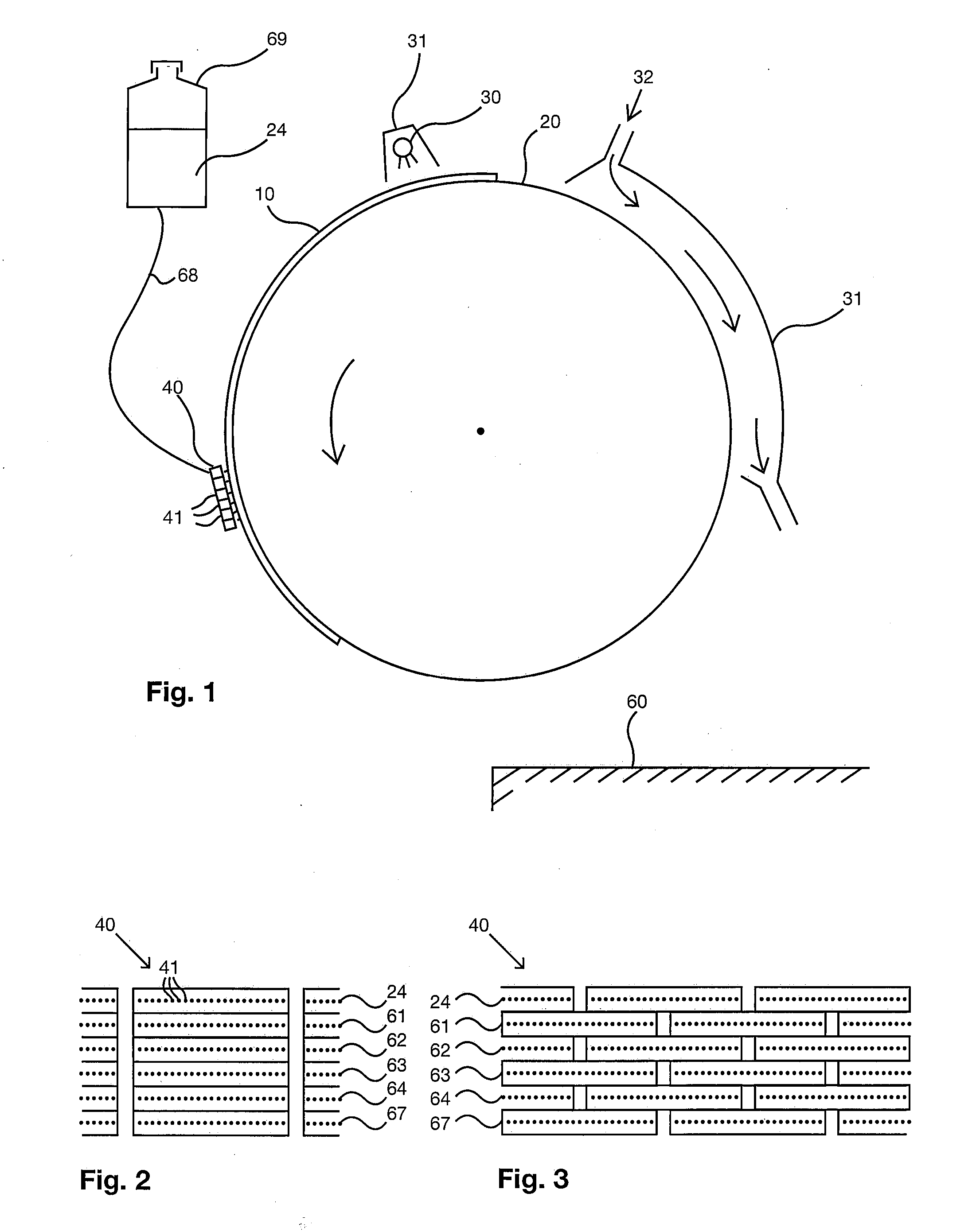
[0042]In the invention, an inkjet cylindrical printer comprises a cylindrical drum and means of firmly locating a substrate sheet on the drum, for example an aluminum or carbon composite drum being perforated and having a vacuum suction system. A first type of inkjet cylindrical printer comprises a plurality of printheads supplying CMYK and white (W) solvent inkjet ink. Optionally, the inkjet cylindrical printer has a solvent ink curing arrangement enabling the first layer of ink to be cured or partially cured while the substrate sheet is still located on the cylinder, for example by hot air blowers disposed along the length of the cylinder, typically remote from the printheads to avoid drying up the inkjet nozzles. A base layer of white ink is first printed in a first layer within a print pattern during a plurality of rotations of the cylinder, during which only white ink is printed onto the substrate sheet. A manual, software or firmware instruction is provided to the machine to p...

second embodiment

[0055]the invention is similar but comprises a second type of inkjet cylindrical printer printing UV-curable ink. UV curing lamps are typically located in a UV lamp head remote from the printhead array such that the UV ink applied in a single rotation of the drum is cured after being deposited onto the substrate sheet before the next application of ink in the next single rotation of the drum.

[0056]Whether the ink is solvent ink or UV ink, drum rotation can cease or be continued between printing the two layers.

[0057]Such inkjet cylinder printing machines typically have many more printhead arrays than other types of inkjet machines. For example, the HP Scitex TJ8500 comprises 150 inkjet printheads with 98 nozzles per printhead distributed along the length of the cylinder, whereas other inkjet machines have as few as four and typically not more than twenty-one inkjet printheads. The printheads are optionally heated for optimum rheology of the inkjet ink for printing purposes. Because t...


PUM


Abstract

A panel and method for making the panel are disclosed. The panel includes a substrate sheet partially imaged with a print pattern. The print pattern subdivides the panel into a plurality of discrete printed areas and / or a plurality of discrete unprinted areas. The design is superimposed on or forms a part of said print pattern. The design comprises a design layer. The print pattern includes a base layer. The print pattern includes elongate printed areas orientated lengthways in one direction. The design layer and base layer include inkjet printable ink in elongate ink deposits orientated lengthways in the one direction. The elongate ink deposits may have an aspect ratio of length:width greater than 1.5:1. The base layer may include white ink. The panel may be made using a digital inkjet cylindrical printer that prints the base layer during at least 10 revolutions of the cylinder.

Description

CROSS-REFERENCE [0001]This application claims the benefit of priority to U.S. Provisional Patent Application No. 60 / 893,768, titled “Inkjet Printing Partially Imaged Panels with Superimposed Layers,” filed on Mar. 8, 2007, the entire contents of which are incorporated herein by reference.BACKGROUND OF THE INVENTION[0002]1. Field of the Invention[0003]The present invention relates generally to the field of inkjet printing partially printed panels with superimposed layers, for example see-through graphic panels comprising a design superimposed on a print pattern selectively applied to a substrate.[0004]2. Description of Related Art[0005]Inkjet printing partially imaged panels in the form of see-through graphics panels, for example according to U.S. RE37,186 and U.S. Pat. No. 6,212,805, is disclosed in U.S. Pat. No. 6,507,413, U.S. Pat. No. 6,899,775, PCT / GB2006 / 000601 and U.S. Patent Application No. 2006 / 0260489. PCT / GB2006 / 000601 and U.S. Patent Application No. 2006 / 260489 also discl...

Claims


Application Information

Patent Timeline
IPC IPC(8): B41J2/195
CPCB41J11/002B41J3/407B41J11/00214
Inventor HILL, G. ROLANDREYNOLDS, PHILLIP JOHN
Owner CONTRA VISION
Learn More