
Method for evaluating a capacity value of a capacitive sensor electrode

a capacitive sensor and capacity value technology, applied in the direction of resistance/reactance/impedence, pulse technique, instruments, etc., can solve the problems of product irradiation of electromagnetic waves subject to normative limitations, unsatisfactory alternate electromagnetic fields, and special effects, etc., to achieve the maximum value of frequency-dependent irradiation power density, the effect of broadening the bandwidth of the signal spectrum and reducing heigh

Active Publication Date: 2019-04-18
HUF HULSBECK & FURST GMBH & CO KG
View PDF0 Cites 1 Cited by
  • Summary
  • Abstract
  • Description
  • Claims
  • Application Information

AI Technical Summary

Benefits of technology

The patent is about a new method for evaluating the capacity of sensor electrodes used in electronic devices. This method uses a variation of charging pulse durations to influence the radiation characteristic of the sensor electrode during the evaluation process. By doing this, the method reduces the maximum values of frequency-dependent irradiation power density and spreads the frequency peaks, resulting in a wider distribution of irradiation energy density and reduced harmonic irradiation. The method also allows for a more flexible configuration of the sensor electrode and increased evaluation speed. Overall, the method provides better accuracy and reliability in evaluating the capacity of sensor electrodes in electronic devices.

Problems solved by technology

Due to the high-frequency charging of the sensor electrode, the problem arises—tendentially more pronounced at higher frequencies—that due to the high-frequency cyclical charging and possible discharging, undesired alternate electromagnetic fields are generated.
This effect may be particularly problematic due to the fact that products irradiating electromagnetic waves are subject to normative limitations.

Method used


Image

  • Method for evaluating a capacity value of a capacitive sensor electrode
  • Method for evaluating a capacity value of a capacitive sensor electrode
  • Method for evaluating a capacity value of a capacitive sensor electrode

Examples


Embodiment Construction

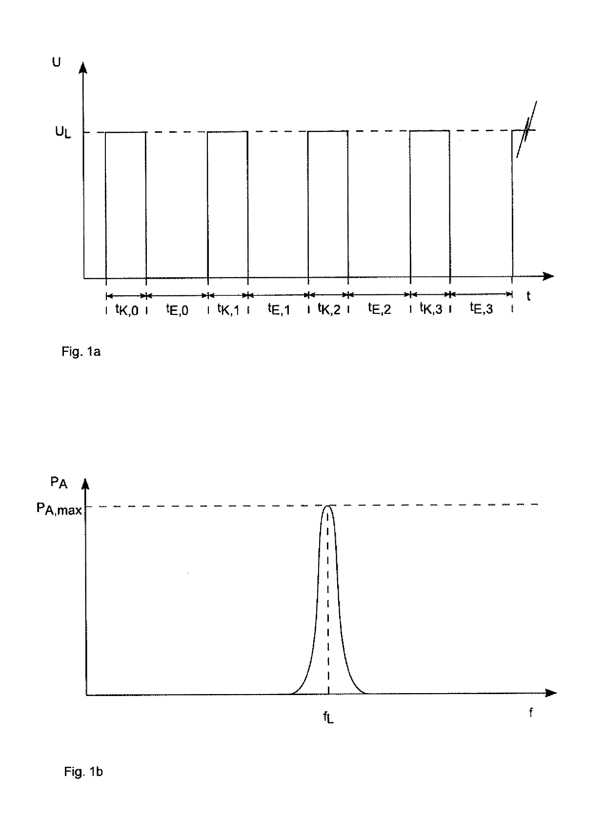
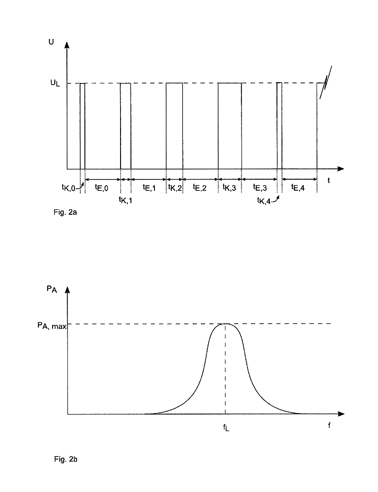
[0063]FIG. 1a shows a representation of coupling and decoupling durations during a portion of a charging process of a sensor electrode for evaluating its capacity. A voltage U, which is applied on the sensor electrode, is shown as a function of time t. As shown, a charging voltage UL is applied for a coupling duration tK,i on the sensor electrode, whereupon during a decoupling duration tE,i the charging potential is separated from the sensor electrode. The procedure is repeated for a number of coupling and decoupling cycles, wherein in FIG. 1a the coupling and decoupling cycles 1 to 4 are shown, with tK,i and tE,i for i=0 . . . 3. In the representation of FIG. 1a, tK,1=tK,2=tK,3=tK,4=tK,i for all i=0 . . . N−1 of all N coupling and decoupling cycles of the evaluation process. In the same way, tE,1=tE,2=tE,3=tE,4=tE,1 for all i=0 . . . N−1. From the control performed according to FIG. 1a of the coupling of the sensor electrode with the charging circuit, an irradiation characteristic ...


PUM


Abstract

A method for evaluating a capacity value of a capacitive sensor electrode includes an evaluation process, which includes performing a charging process of a sensor electrode, and evaluating a parameter, which depends on the capacity value of the sensor electrode. A first charging pulse duration tL,1 for the charging process includes a first coupling duration tK,1 and a first decoupling duration tE,1 with tL,1=tK,1+tE,1, of a first coupling and decoupling cycle. A second charging pulse duration tL,2, includes a second coupling duration tK,2 and a second decoupling duration tE,2 with tL,2=tK,2+tE,2, of a second coupling and decoupling cycle immediately following the first coupling and decoupling cycle. These differ from each other by a first pulse duration difference ΔtL,1.

Description

BACKGROUND[0001]The invention refers to a method for evaluating a capacity value of a capacitive sensor electrode.[0002]The use of capacitive sensor electrodes is known in practice for various applications.[0003]An example of the use of capacitive sensor electrodes are capacitive proximity switches, which are mounted on vehicles, in order to detect the presence of a person, for example. The function of such a capacitive proximity sensor is based on the fact that the capacity of a capacitive sensor electrode of the proximity sensor reaches a certain value or exceeds the same or experiences a predetermined absolute or relative change.[0004]In order to evaluate the capacity at a certain time or during a specific time interval, the capacitive sensor electrode is coupled to a predetermined potential. The sensor electrode forms a capacity with a reference electrode. The reference electrode, in the example of a proximity sensor on a vehicle, may be a vehicle ground or a ground of the terra...

Claims


Application Information

Patent Timeline
Patent Type & Authority Applications(United States)
IPC IPC(8): G01R27/26
CPCG01R27/2605H03K17/955H03K2217/960705H03K2217/960725
Inventor SIEG, BERTHOLD
Owner HUF HULSBECK & FURST GMBH & CO KG
Learn More