Depolarised WDM source

a wdm source and depolarised technology, applied in the direction of fiber transmission, transmission, distortion/dispersion elimination, etc., can solve the problems of limiting the efficacy of wdm signal in transmitting data from transmitter to receiver, affecting the effect of wdm signal in transmitting data, and becoming more significant, so as to achieve effective depolarisation and minimise the net pdg of the link

Inactive Publication Date: 2013-02-19
NEPTUNE SUBSEA IP LTD
View PDF5 Cites 1 Cited by
  • Summary
  • Abstract
  • Description
  • Claims
  • Application Information

AI Technical Summary

Benefits of technology

[0011]The DGD element of the present invention alters the polarisation state of the source signals by an amount that depends on their frequency. Each source signal is therefore affected differently so that, while individual channels remain polarised, the resulting total optical field of the overall multiplexed signal is depolarised. This technique reduces the impact of non-linear effects on the data channels, since adjacent data channels will have different polarisation states by virtue of their differing frequencies. Moreover, the present invention overcomes the problems of PDG and PHB by introducing means to depolarise the overall WDM signal. The damaging consequences of PDG, such as fluctuations in the optical power of the data channels (which can affect the OSNR and the BER), are therefore eliminated.
[0012]The present invention therefore simultaneously provides a simple, integrated, low cost solution to a number of the problematic effects observed in WDM systems.
[0013]The benefits of the present invention with respect to PDG and PHB are particularly apparent in low channel count systems. For example, the lower the number of channels in a system, the higher the statistical probability of the channels being aligned in the detrimental way described above. Furthermore, each loading channel will provide more of the total system power, thereby having a greater effect on the saturation of the line amplifiers. In a low channel count system there is also a greater chance that a single loading channel will be the sole occupant of a spectral region, thus causing strong PHB.
[0015]As a consequence of using sources suitable for WDM, the present invention allows loading channels to be converted into data channels (or vice versa) as and when the need arises. Moreover, these sources have narrow linewidths and high OSNRs. They also offer stable and accurate wavelength and power control.
[0017]In a preferred embodiment of the present invention, a number of groups of loading channels are utilised, where the members of each group lie within a wavelength range that is substantially smaller than the wavelength range separating the groups and each group is effectively depolarised by the DGD. This allows loading channels to be spread across the entire transmission spectrum while minimising the effect that any polarisation mode dispersion (PMD) in the fibre may have on the relative polarisation of the loading channels.
[0018]Preferably, the power and wavelength of each channel may be tuned. Tuning these parameters will affect the output polarisation of that channel, and therefore the overall degree of polarisation (DOP) of the multiplexed output signal. Accordingly, fine tuning of these parameters may be used to cancel out effects due to PMD in the fibre, thereby minimising the net PDG for the link.

Problems solved by technology

Each data channel carries independent information, but non-linear effects in typical transmission media can lead to interference between these channels.
These non-linear effects corrupt the signal, limiting the efficacy of the WDM signal in transmitting data from transmitter to receiver.
Moreover, they become more significant as the frequency separation between data channels decreases, thereby acting as a limit on the number of data channels (and thus the amount of information) that can be carried by a given WDM signal.
Filtered ASE sources typically have poor stop band rejection and broad linewidths that limit data channel performance.
One major issue for a multi-channel repeatered system is Polarisation Dependent Gain (PDG), which is due to an effect known as Polarisation Hole Burning (PHB) whereby the available gain is saturated and depleted for a particular polarisation.
Over time, system-varying effects change the relative states of polarisation between the channels, leading to a fluctuation in the optical power of the data channel.
Even worse, the variation in channel power can affect the Optical Signal-to-Noise Ratio (OSNR) of the channel and also the strength of non-linear effects leading to changes in the Bit Error Rate (BER) performance of the channel.

Method used


Image

  • Depolarised WDM source
  • Depolarised WDM source
  • Depolarised WDM source

Examples


Embodiment Construction

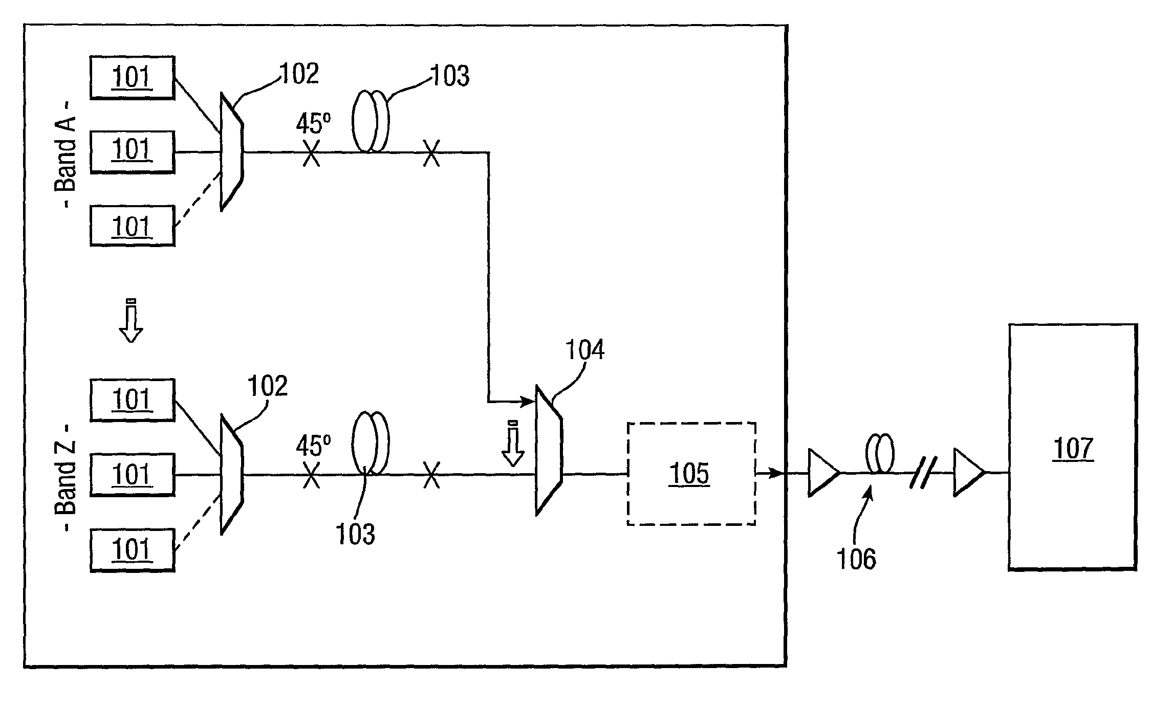
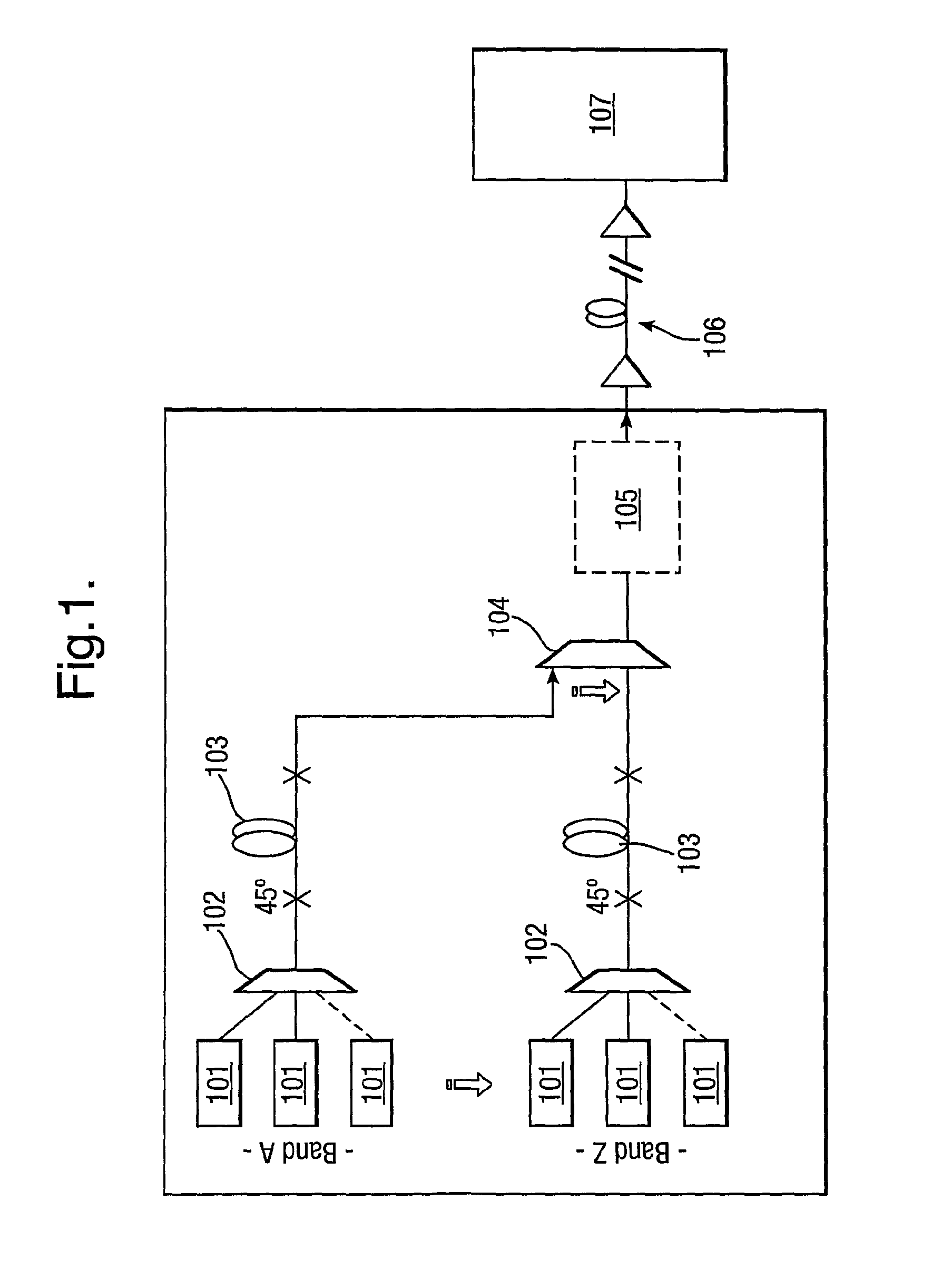
[0037]FIG. 1 shows a typical example of a Submarine Line Terminal Equipment (SLTE) transmission system. The channels may be any combination of loading and data channels. In the example shown, there are separate “bands” each comprising a plurality of channels. A WDM signal is formed of each band before the bands are multiplexed together to form the final signal.

[0038]As shown, a plurality of channel sources 101 in each band provide parallel polarised optical source signals that are multiplexed together by a polarisation maintaining multiplexor 102, thereby providing a polarised WDM signal. This polarised signal then passes through a DGD element 103 in order that the WDM signal may be depolarised, while the time-averaged DOP of each channel within the WDM signal remains substantial.

[0039]The depolarised WDM signals from each band are then combined by a further multiplexor 104. The combined signal passes through various other aggregate equipment 105 before being launched across a trans...


PUM


Abstract

A device and method for depolarising the total field of a wavelength division multiplexed (WDM) signal is provided. A polarization maintaining multiplexor combines a plurality of optical signals to form a polarized multiplexed signal. The multiplexed signal is then passed through a differential group delay (DGD) element adapted to modify the polarization state of one or more optical source signals within the multiplexed signal and thereby to at least partially depolarise the multiplexed signal.

Description

FIELD OF THE INVENTION[0001]The present invention relates to wavelength division multiplexed (WDM) sources, and in particular to their use in ultra long haul (ULH) communications systems.BACKGROUND OF THE INVENTION[0002]A WDM signal will typically contain a number of data channels, that is optical signals that have been modulated in such a way as to carry information. Each data channel carries independent information, but non-linear effects in typical transmission media can lead to interference between these channels. These effects include four-wave mixing (FWM) and cross phase modulation (XPM). FWM is a non-linear effect that may occur when two or more signals of different frequencies pass through an optical fibre and which has the effect of generating a signal at a new frequency. These non-linear effects corrupt the signal, limiting the efficacy of the WDM signal in transmitting data from transmitter to receiver. Moreover, they become more significant as the frequency separation b...

Claims


Application Information

Patent Timeline
Patent Type & Authority Patents(United States)
IPC IPC(8): H04J14/02H04J14/06H04B10/2507H04B10/50
CPCG02B6/274G02B6/278G02B6/2786H04B10/2572H04B10/506H04J14/02
Inventor DESBRUSLAIS, STEPHENOBERLAND, RICHARDBARNES, STUART ROBERTWEBB, STEPHEN MICHAEL
Owner NEPTUNE SUBSEA IP LTD
Why Eureka
Try Eureka