

Imaging on flexible packaging substrates
a flexible packaging and substrate technology, applied in the direction of printing, inks, instruments, etc., can solve the problems of poor scratching, rub and smear resistance, irregular dot growth, poor image robustness of liquid toners, etc., and achieve the effect of high image quality and well-registered colors
- Summary
- Abstract
- Description
- Claims
- Application Information
AI Technical Summary
Benefits of technology
Problems solved by technology
Method used
Image

Examples
example 1
[0156]The ultraviolet-curable gel based phase change ink was formulated as follows: an amide gellant (16.88 g), Unilin 350-acrylate (prefiltered to 2 μm, 11.25 g), propoxylated neopentyl glycol diacrylate (142.88 g, SR9003, obtained from Sartomer Co. Inc., Exton, Pa.), 2-dimethylamino-2-(4-methylbenzyl)-1-(4-morpholin-4-ylphenyl)-butanone (6.75 g, IRGACURE® 379, obtained from Ciba Specialty Chemicals, Tarrytown, N.Y.), isopropyl-9H-thioxanthen-9-one (4.50 g, DAROCUR® ITX, obtained from Ciba Specialty Chemicals, Tarrytown, N.Y.), bis(2,4,6-trimethylbenzoyl)-phenyl-phosphine oxide (2.25 g, IRGACURE® 819, obtained from Ciba Specialty Chemicals, Tarrytown, N.Y.), 2-hydroxy-1-(4-(4-(2-hydroxy-2-methylpropionyl)-benzyl)-phenyl)-2-methylpropan-1-one (7.88 g, IRGACURE® 127, obtained from Ciba Specialty Chemicals, Tarrytown, N.Y.), and IRGASTAB® UV10 (0.45 g, obtained from Ciba Specialty Chemicals, Tarrytown, N.Y.) were stirred at 90° C. for 2 hours, after which time the solutions were filte...
example 2
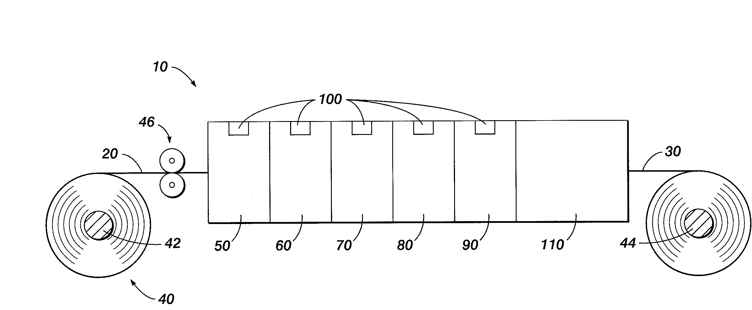
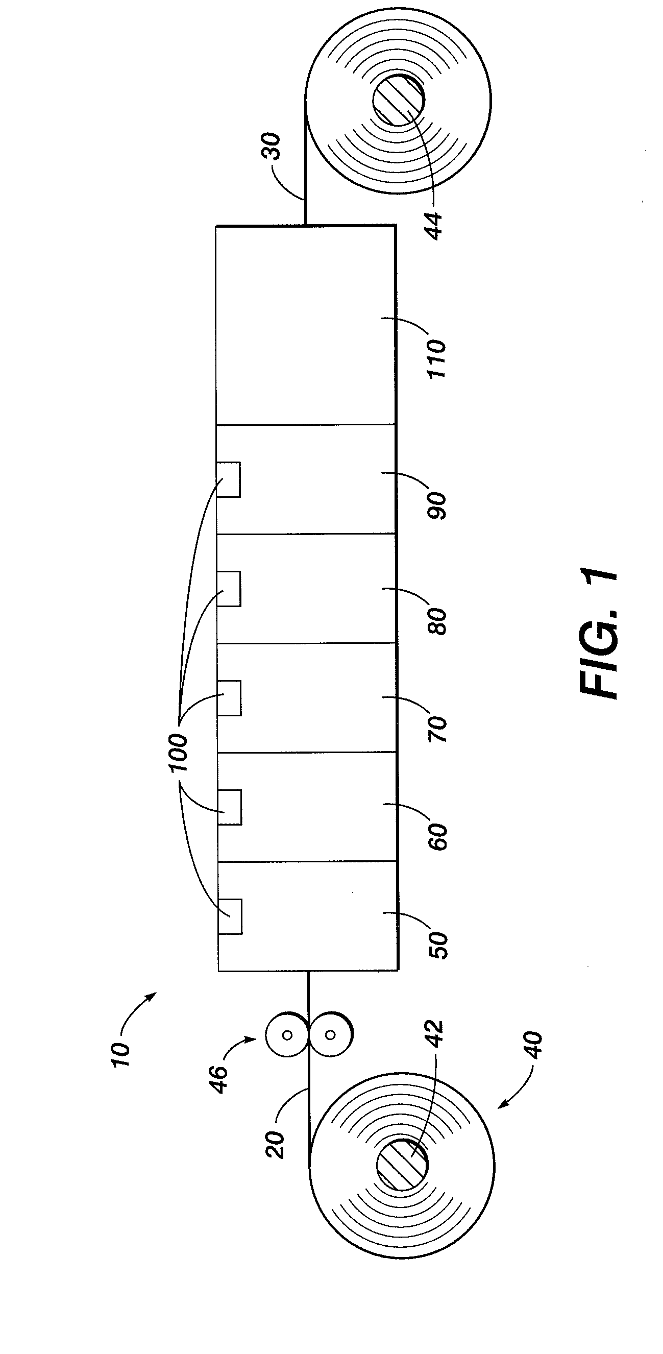
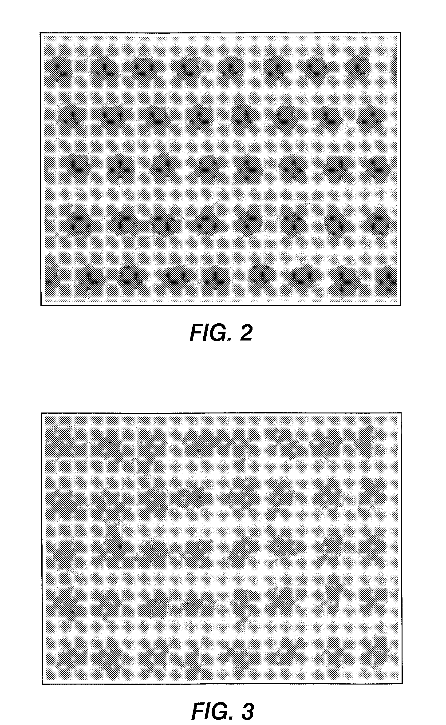
[0157]The ink of Example 1 was printed on a variety of media. The media were: (a) Xerox Color Xpressions Plus™ plain paper; (b) McCoy Gloss Text coated paper; (c) Melinex™ 813 (polyester of 12 microns thickness); (d) aluminum foil (40 microns thick); and (e) OPPalyte™ ASW 250 (polypropylene of 43 microns thickness). As comparison, a conventional low viscosity UV-curable cyan ink obtained from a well known UV curable ink manufacturer was used. The UV gel and the conventional low viscosity ink were printed from a piezoelectric printhead directly onto the substrate without pinning. The ink drops were ˜21 nanograms each, printed at 150 dots per inch (dpi) in the cross process direction, and at 200 dpi in the process direction. For the phase change ink of Example 1, the printhead was heated at 75° C. For the conventional low viscosity ink, the printhead was heated at 45° C.
[0158]FIG. 2 is the phase change ink printed on plain paper. FIG. 3 is the conventional low viscosity ink printed on...
example 3
[0166]Two phase change inks, one cyan and one magenta, were formulated and printed on the five substrates. Three lines were printed. The top line was the cyan ink, the middle line was the magenta ink, and the bottom line was either printed (i) with the magenta ink on top of the cyan ink to form blue; or (ii) with the cyan ink by itself. All images were then cured with an in-line UV curing lamp. The appearance of the colors is slightly affected by the substrate on which it is printed.
[0167]FIG. 12 shows the phase change inks printed on plain paper, with the top line cyan, the middle line magenta, and the bottom line cyan.
[0168]FIG. 13 shows the phase change inks printed on glossy paper, with the top line cyan, the middle line magenta, and the bottom line blue.
[0169]FIG. 14 shows the phase change inks printed on polyester substrate, with the top line cyan, the middle line magenta, and the bottom line blue.
[0170]FIG. 15 shows the phase change inks printed on aluminum substrate, with th...
PUM
| Property | Measurement | Unit |
|---|---|---|
| Temperature | aaaaa | aaaaa |
| Temperature | aaaaa | aaaaa |
| Color | aaaaa | aaaaa |
Abstract
Description
Claims
Application Information