
Thermal management system for LED array

a technology of led arrays and management systems, applied in semiconductor devices, semiconductor/solid-state device details, lighting and heating apparatus, etc., can solve the problems of increasing the thermal load that must be dissipated, the significant challenge of thermal management of led arrays, and the phase change of the heated surfa

Active Publication Date: 2008-09-11
NUVENTIX
View PDF6 Cites 41 Cited by
  • Summary
  • Abstract
  • Description
  • Claims
  • Application Information

AI Technical Summary

Benefits of technology

"The present patent relates to thermal management devices, particularly for LED arrays, which are used in display systems. The technical problem addressed in the patent is the need for more efficient cooling solutions for heat-producing bodies in microelectronics and other industries. The patent describes a method called two-phase heat transfer, which involves the evaporation of a liquid in a hot region and the condensation of the resulting vapor in a cooler region. This method has been studied for its benefits in thermal management for many years. The patent also describes the construction of an illumination optical system for a display system, which uses synthetic jets to improve cooling. The technical effects of the patent are improved cooling for LED arrays and other heat-producing bodies, as well as improved brightness distribution uniformity for display systems."

Problems solved by technology

Thermal management is recognized as a major challenge in the design and packaging of state-of-the-art integrated circuits in single-chip and multi-chip modules.
First, the liquid to vapor phase change greatly increases the heat flux from the heated surface.
One particularly significant challenge in thermal management exists with respect to LED arrays.
However, doing so increases the thermal load that must be dissipated by the display's thermal management system.
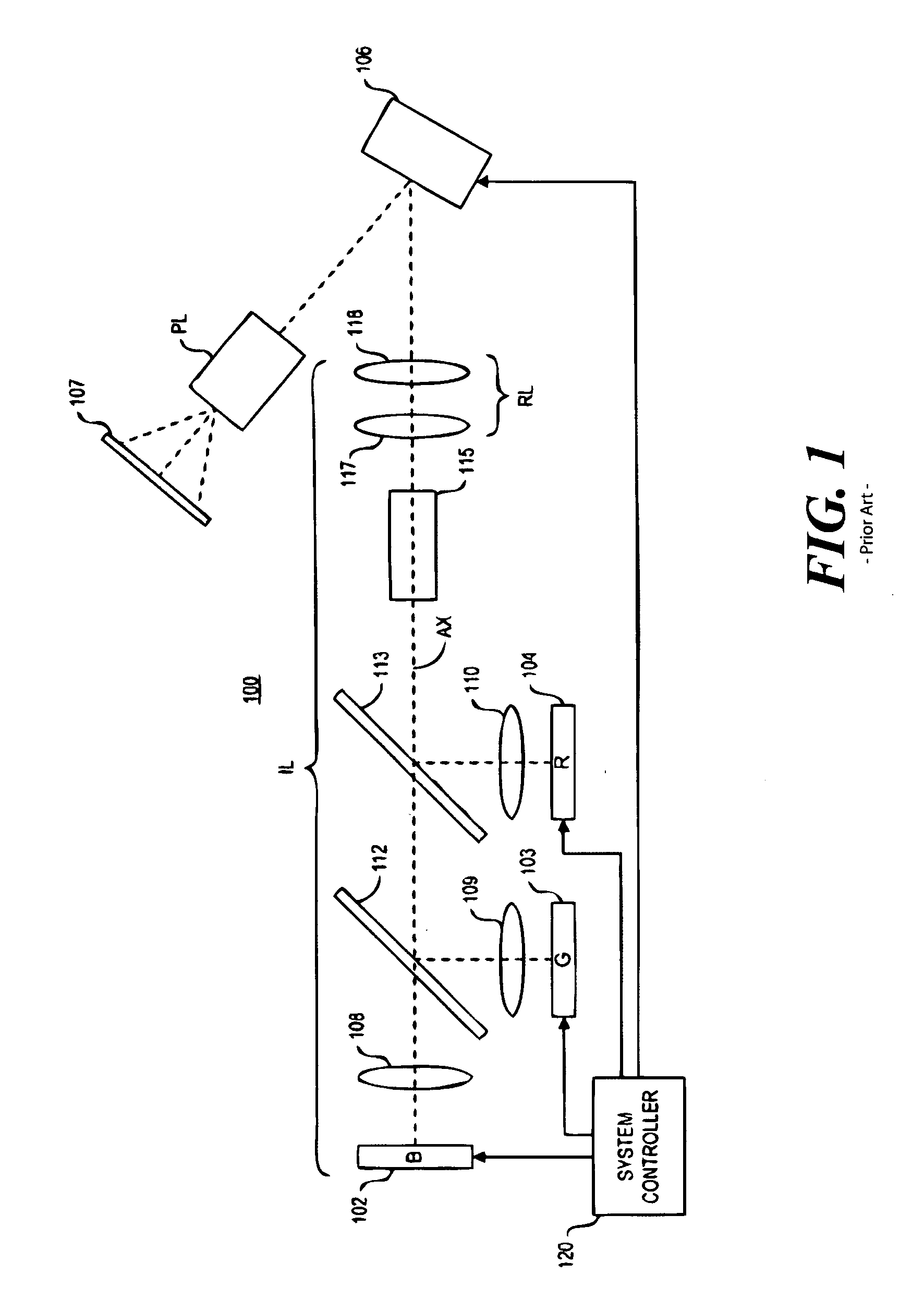
Currently, the limitations of existing thermal management systems limits the optical flux permissible at the light sources 102-104.
These limitations, in turn, place limitations on the performance of the SLM display system 100.

Method used


Image

  • Thermal management system for LED array
  • Thermal management system for LED array
  • Thermal management system for LED array

Examples


Embodiment Construction

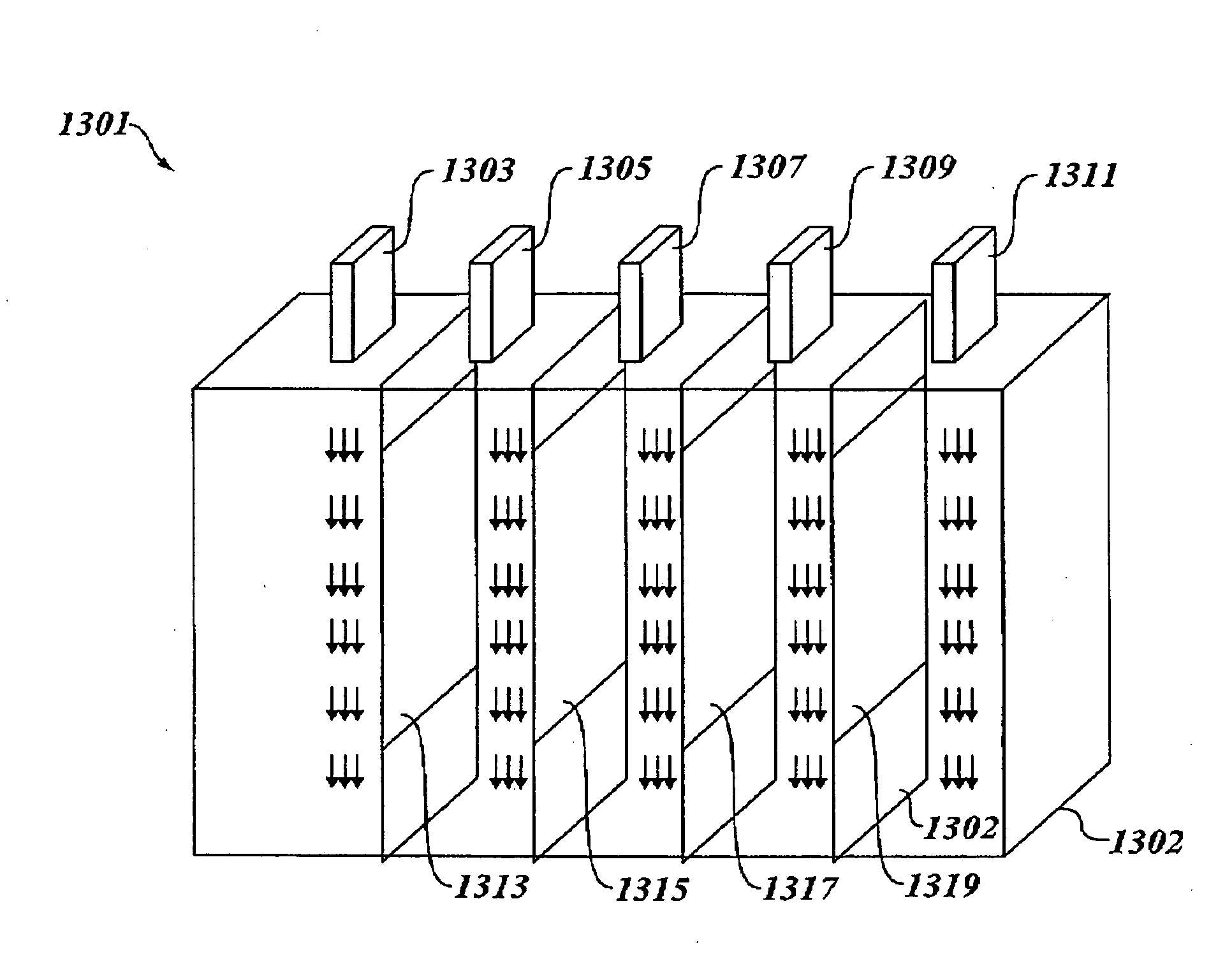
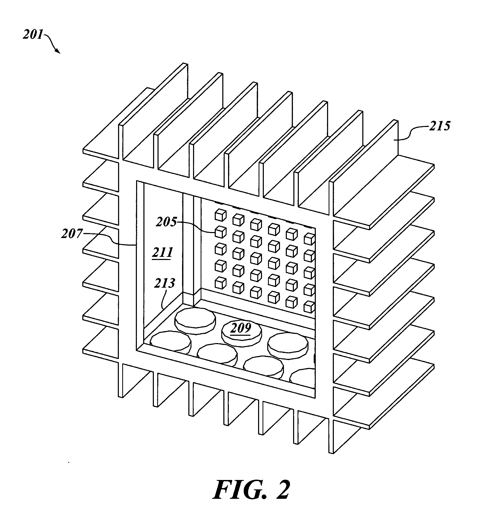
[0037]In one aspect, a device is provided which comprises (a) a chamber having a liquid disposed therein, (b) an LED array having a first surface which is in contact with said liquid, and (c) at last one actuator adapted to dislodge vapor bubbles from said first surface through the emission of pressure vibrations.

[0038]In another aspect, a method for thermally managing an LED array is provided. In accordance with the method, a chamber is provided which comprises an LED array, said chamber having a liquid disposed therein. Vapor bubbles are caused to form on a surface of said LED array, and acoustic or pressure vibrations are emitted into the liquid, thereby dislodging the vapor bubbles from the surface of the LED array.

[0039]In a further aspect, a device is provided which comprises (a) an LED array having a light emitting surface, (b) an actuator array, and (c) a window, disposed in opposing relation to said light emitting surface; wherein said light emitting surface, said actuator ...


PUM


Abstract

A device, comprising (a) a chamber having a liquid disposed therein, (b) an LED array having a first surface which is in contact with said liquid, and (c) at last one actuator adapted to dislodge vapor bubbles from said first surface through the emission of pressure vibrations.

Description

FIELD OF THE DISCLOSURE[0001]The present disclosure relates generally to thermal management devices, and more particularly to methods for making synthetic jet ejectors.BACKGROUND OF THE DISCLOSURE[0002]Thermal management of heat-producing bodies is a concern in many different technologies. Particularly in microprocessors, the rise in heat dissipation levels accompanied by a shrinking thermal budget has resulted in the need for new cooling solutions beyond conventional thermal management techniques. In the microelectronics industry, for example, advances in technology have brought about an increase in transistor density and faster electronic chips. As electronic packages increase in speed and capability, the heat flux that must be dissipated to maintain reasonable chip temperatures has also risen. Thermal management is recognized as a major challenge in the design and packaging of state-of-the-art integrated circuits in single-chip and multi-chip modules.[0003]One method for effectiv...

Claims


Application Information

Patent Timeline
Patent Type & Authority Applications(United States)
IPC IPC(8): F21V29/00
CPCF21K9/00H01L23/427H01L33/648H04N9/315H01L2924/0002H04N9/3197H01L2924/00
Inventor HEFFINGTON, SAMUEL N.MAHALINGAM, RAGHAVENDRANJONES, LEE M.DARBIN, STEPHEN
Owner NUVENTIX
Learn More