Bone drilling cannula

a cannula and bone technology, applied in bone drill guides, infusion syringes, medical science, etc., can solve the problems of significant skid off of bone, inaccurate hole position, and slippage of guide sleeves

Active Publication Date: 2008-09-11
MAZOR ROBOTICS
View PDF12 Cites 24 Cited by
  • Summary
  • Abstract
  • Description
  • Claims
  • Application Information

AI Technical Summary

Benefits of technology

[0009]The present invention seeks to provide a new surgical drilling guide cannula, having a serrated distal end in the form of sharpened teeth for providing firm contact with the bone surface to be drilled, and which enables all or most of the teeth to maintain biting contact with the bone surface, essentially independently of the curvature of the bone surface, and essentially independently of the required drilling angle. The drilling guide cannula of the present invention comprises a bore through which the drilling is performed. The cannula outer wall preferably has a thickness sufficient to incorporate a number of secondary pins arranged circumferentially around the drilling bore. These pins slide axially relative to the cannula, preferably in bored holes formed within the wall of the cannula, or in channels formed therein. Each of the secondary pins has a sharpened distal end. The cannula is applied to t

Problems solved by technology

In such use, the above mentioned problem of skiving off the bone can be significant.
However, when the hole has to be drilled into a small diameter bone having a distinctly curved outer surface, or even when the hole is to be drilled in a flat bone surface, but at a signif

Method used


Image

  • Bone drilling cannula
  • Bone drilling cannula
  • Bone drilling cannula

Examples


Embodiment Construction

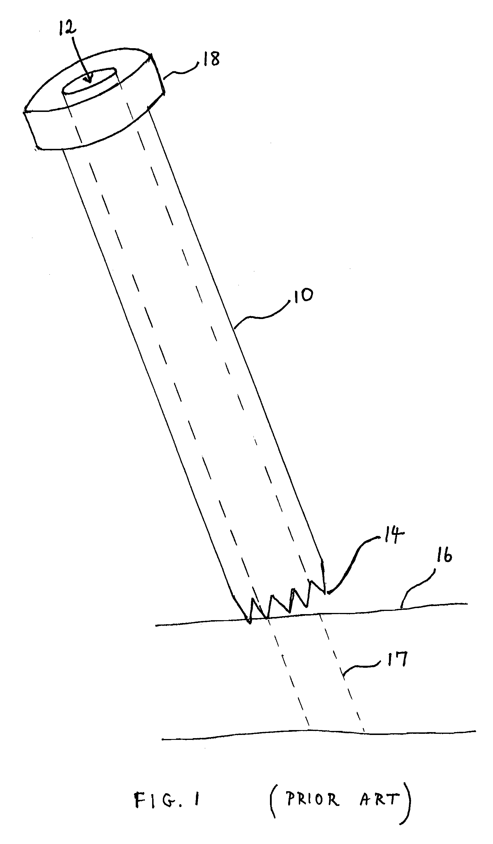
[0026]Reference is now made to FIG. 1, which illustrates schematically a prior art drill guide, such as is described in some of the references cited hereinabove. The drill guide 10 has a bore 12 through which the drill or other surgical tool is inserted and guided. At its distal end, the drill guide has a number of circumferentially disposed teeth, generating a serrated edge 14. At its proximal end, the guide preferably has a knurled knob 18 for gripping the guide, or for pushing or striking it, so that the teeth bite into the bone to be operated on, thereby providing positional stability to the guide. In FIG. 1, the guide is shown being applied to the bone 16 of a subject at the angle required to drill the hole 17 desired. Because this angle is not normal to the surface of the bone, and also because of the small diameter of the bone, only a small number of the teeth of the serrated edge, or even just a single tooth, may be in contact with the bone, biting into it to provide positio...


PUM


Abstract

A drilling guide cannula, having a serrated distal end in the form of axially moveable teeth which enables all or most of the teeth to maintain biting contact with the bone surface, essentially independently of the curvature of the bone surface and the drilling angle. The cannula outer wall incorporates a number of pins arranged circumferentially around the drilling bore. These pins slide axially relative to the cannula, preferably in bored holes or in channels formed within the wall of the cannula. Each of the secondary pins has a sharpened distal end, each constituting a moveable tooth. The cannula is applied to the bone to be drilled at the desired drilling position and angle, and the pins are forced axially towards the bone surface. The pins take up the contour of the bone surface and each pin bites into the bone surface to rigidly position the drilling guide cannula.

Description

FIELD OF THE INVENTION[0001]The present invention relates to the field of devices for enabling accurate drilling in orthopaedic surgical procedures, especially for drilling into a bone at angles away from the normal to the bone surface.BACKGROUND OF THE INVENTION[0002]In many orthopaedic surgical procedures, there is need to drill holes in the bone of the patient, in order to insert fixation devices or surgical inserts. Surgical screws are widely used in orthopedic surgery to fix broken bones as well as to maintain the broken bones in alignment during the healing process. The hole for receiving these inserts or fixation devices are generally prepared by drilling through a cannulated drill guide, and many such drill guides have been described in the prior art.[0003]In U.S. Pat. No. 5,403,322 to J. E. Herzenberg et al, for “Drill guide and method for avoiding intramedullary nails in the placement of bone pins”, there is described a drill sleeve or a guide-wire sleeve having a toothed ...

Claims


Application Information

Patent Timeline
IPC IPC(8): A61B17/58A61M5/178
CPCA61B17/17
Inventor SHOHAM, MOSHE
Owner MAZOR ROBOTICS
Why Eureka
Try Eureka