Polyaxial screwdriver for a pedicle screw system

Active Publication Date: 2008-09-11
STRYKER EURO OPERATIONS HLDG LLC
View PDF9 Cites 37 Cited by
  • Summary
  • Abstract
  • Description
  • Claims
  • Application Information

AI Technical Summary

Benefits of technology

[0013]In yet another embodiment of a polyaxial screwdriver, the outer sleeve of the polyaxial screwdriver has a split end. The split end securely engages the coupling element. A short ring is located around the split end of outer slee

Problems solved by technology

Patients that suffer from such conditions usually experience extreme and debilitating pain, as well as diminished nerve functio

Method used


Image

  • Polyaxial screwdriver for a pedicle screw system
  • Polyaxial screwdriver for a pedicle screw system
  • Polyaxial screwdriver for a pedicle screw system

Examples


Embodiment Construction

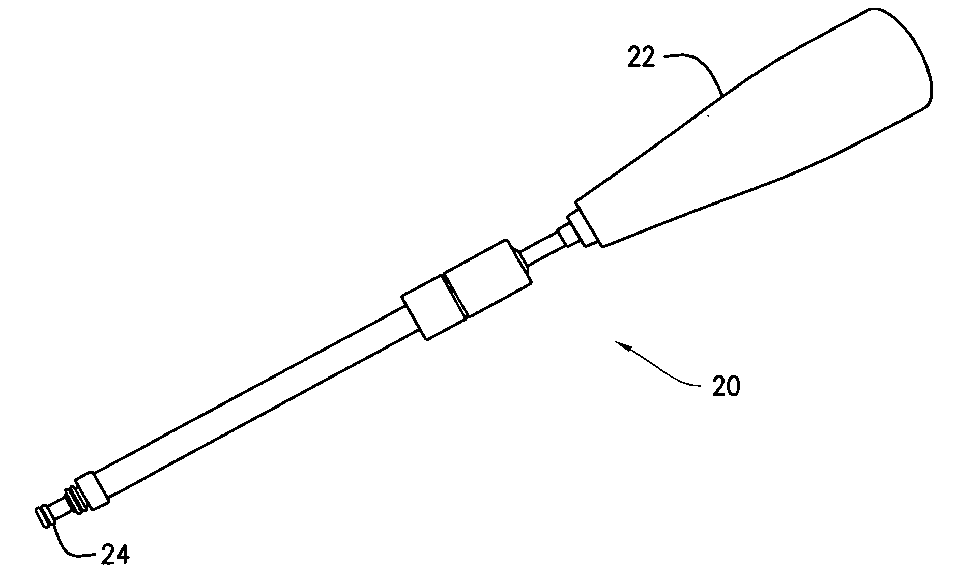
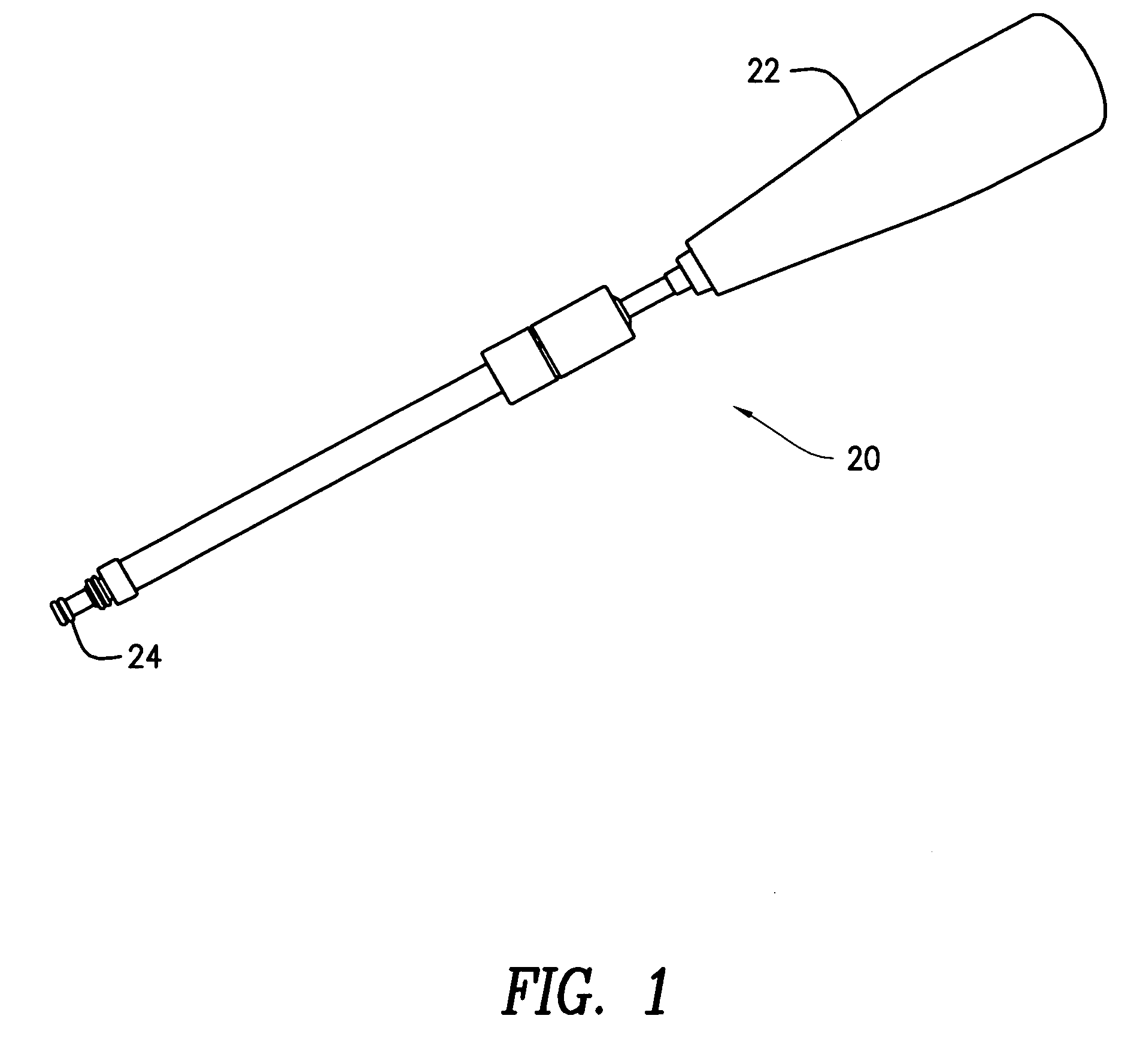
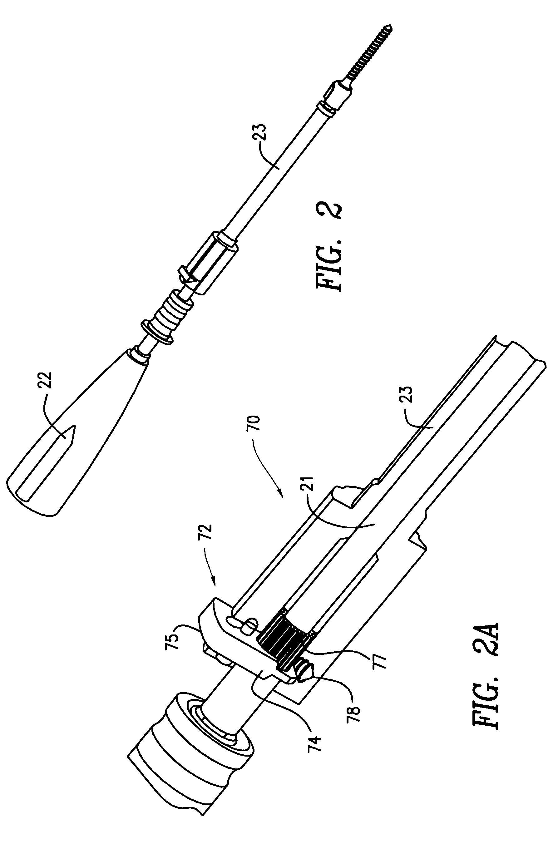
[0028]FIG. 1 shows a polyaxial screwdriver 20. The polyaxial screwdriver 20 has a handle 22 and a screw engaging end 24. The screw engaging end 24 engages the head of a polyaxial screw such that when the screwdriver 20 is rotated via the handle 22, the polyaxial screw is advanced or retracted in the vertebra. The polyaxial screwdriver 20 has an internal shaft 21 (FIG. 2A) that connects to the handle 22 and has a screw engaging end 24 (FIG. 3) formed on the end opposite the handle 22. An outside sleeve 23 is slidably inserted over the internal shaft 21.

[0029]The screw engaging end 24 has a hollow cylindrical portion 26. The hollow cylindrical portion 26 has a cylindrical external surface 28. The internal surface of the hollow cylindrical portion 26 has semi-cylindrical cutouts 30 that are spaced at a distance from each other. Placed between the semi-cylindrical cutouts 30 are cylindrical structures 32. The cylindrical structures 32 project beyond the edge of the semi-cylindrical cuto...


PUM


Abstract

A polyaxial screwdriver for inserting a bone screw in a vertebra. A polyaxial bone screw assembly includes a coupling element. When a screw engaging end of the polyaxial screwdriver is lowered on the head of the bone screw, the complimentary surfaces of the screw engaging end of the screwdriver and the head of the screw self-align. A ratchet mechanism formed in the screwdriver provides progressive and automatic locking of the polyaxial screwdriver to the coupling element and prevents the accidental unthreading from the coupling element. In another embodiment of the polyaxial screwdriver, a collet slides over the outside surface of the upper end of the coupling element and locks on to the coupling element. In yet another embodiment of a polyaxial screwdriver, the outer sleeve of the polyaxial screwdriver has a split end that securely engages the coupling element.

Description

CROSS-REFERENCE TO RELATED APPLICATIONS[0001]This application claims the benefit of the filing date of U.S. Provisional Patent Application No. 60 / 881,106 filed Jan. 18, 2007, the disclosure of which is hereby incorporated herein by reference.BACKGROUND OF THE INVENTION[0002]1. Field of the Invention[0003]The present invention relates generally to spinal fixation devices and more specifically relates to a pedicle screw system having an improved screwdriver coupling interface and securing of the screwdriver to the polyaxial screw assembly.[0004]2. Description of the Related Art[0005]The spinal column is a highly complex system of bones and connective tissues that provides support for the body and protects the delicate spinal cord and nerves. There are many types of spinal column disorders including scoliosis (abnormal lateral curvature of the spine), kyphosis (abnormal forward curvature of the spine, usually in the thoracic spine), excess lordosis (abnormal backward curvature of the s...

Claims


Application Information

Patent Timeline
IPC IPC(8): A61B17/58B25B13/46B25B13/48
CPCA61B17/7032A61B17/7082A61B17/7037A61B2017/564A61B17/7035A61B17/8605A61B17/8888
Inventor SHARIFI-MEHR, AMIR ALICORRAO, ERNIECHOI, ANDY WONYONG
Owner STRYKER EURO OPERATIONS HLDG LLC
Why Eureka
Try Eureka