Method for Establishing a Nail Connection and Nails Therefor

a technology of nail connection and nail, which is applied in the direction of bolts, manufacturing tools, mechanical devices, etc., can solve the problem that the joining method is not suitable for fastening sheet metal plates, and achieve the effect of high quality connection

Active Publication Date: 2008-09-18
BOLLHOFF VERBINDUNGSTECHNIK GMBH
View PDF3 Cites 41 Cited by
  • Summary
  • Abstract
  • Description
  • Claims
  • Application Information

AI Technical Summary

Benefits of technology

[0006]The object of the present invention is to create a method for establishing a connection between two components by means of a nail driven in at a high speed and a nail therefore which can be used in the case of one-sided accessibility of the components, does not require the prepunching of holes in the components, enables above all a short-term joining process without rotational movement of the nail and leads nonetheless to a high quality connection.
[0012]The method according to the invention is characterized by great simplicity and extremely low joining time, since a prepunching of the components is not required and the nail is driven into and through the two components in one single joining process at a high speed without a rotational movement. As corroborated in experiments, the connection between the two components established in this manner is characterized by a high connection quality. Another advantage of the method according to the invention is that two-sided accessibility of the joining area is not required if the component facing away from the nail head is sufficiently rigid.

Problems solved by technology

This joining method is not suitable for fastening sheet metal plates to extruded sections with a closed cross-section or to components that have been reshaped through high internal pressure, as required for example in automobile manufacturing.

Method used


Image

  • Method for Establishing a Nail Connection and Nails Therefor
  • Method for Establishing a Nail Connection and Nails Therefor
  • Method for Establishing a Nail Connection and Nails Therefor

Examples


Embodiment Construction

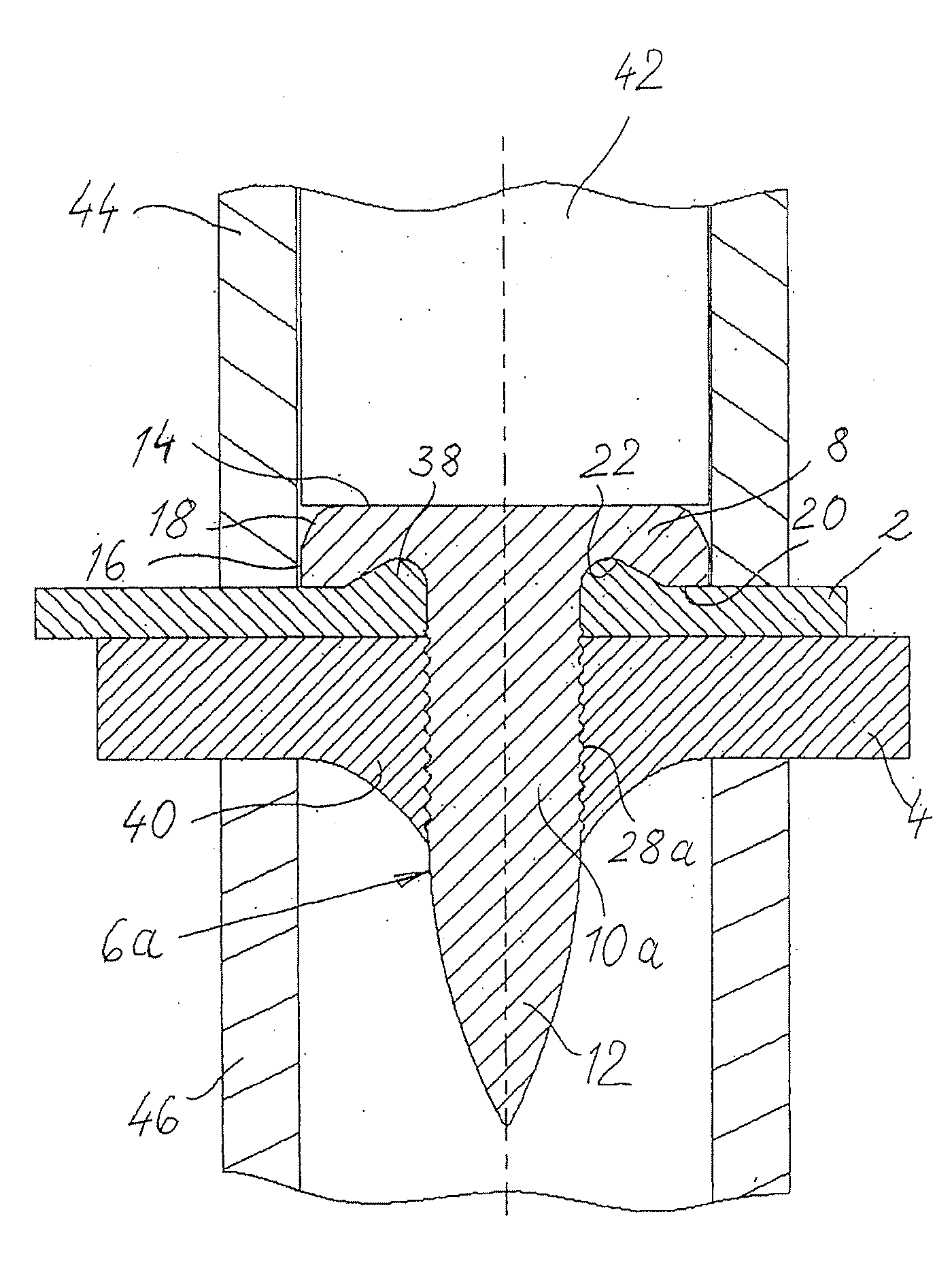
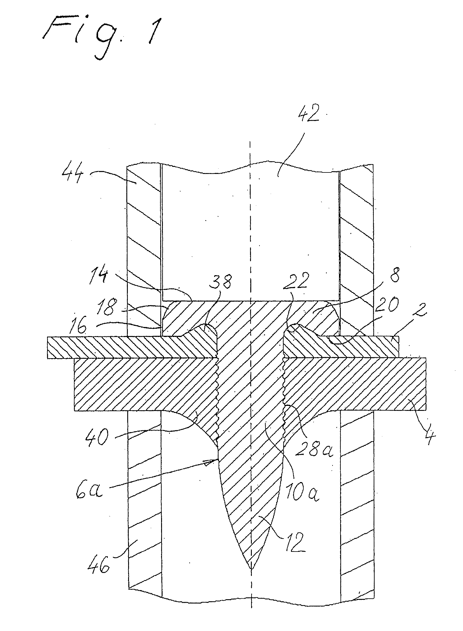
[0028]FIG. 1 shows a finished connection between a component 2 and a component 4 by means of a nail 6a. In the exemplary embodiment shown, the component 2 is a thin-walled component in the form of a sheet metal plate, and the component 4 is a component with a larger wall thickness, which is for example a profile component. They can for example be body parts for automobile manufacturing, while the invention is not restricted to this.

[0029]The components 2, 4 can be made of steel, aluminum, magnesium or plastic with or without fiber content. They are not prepunched before the joining process, as will be explained in greater detail.

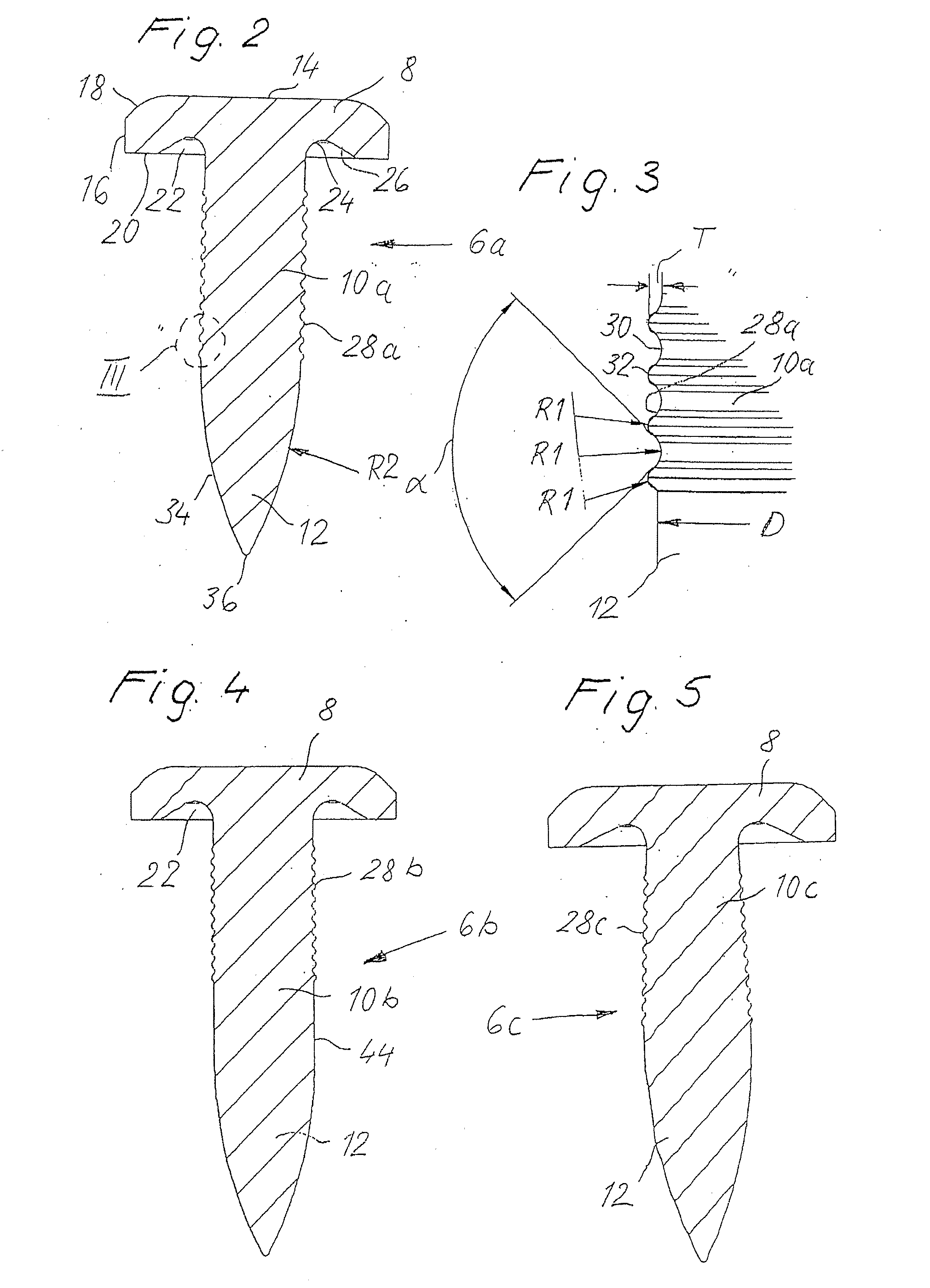
[0030]As can be seen in FIGS. 1 and 2, the nail 6a consists of a nail head 8, a nail shaft 10a and a nail tip 12.

[0031]The nail head 8 is a flat head with an even top side 14, a cylindrical circumferential surface 16 and an even bottom side 20, in which a circular groove 22 is formed adjacent to the nail shaft 10a. The circular groove 22 has a rounded circum...


PUM

PropertyMeasurementUnit
angleaaaaaaaaaa
speedaaaaaaaaaa
speedaaaaaaaaaa

Abstract

A method is described for establishing a nail connection between two components as well as a nail therefor. The nail is driven through the non-prepunched components in the joining area at a high speed such that the nail tip fully penetrates both components and forms a toric-shaped material bulge in the nail-head-side component, which protrudes into a circular groove of the nail head, and a crater-shaped material bulge is formed in the component facing away from the nail head, which protrudes in the opposite direction.

Description

FIELD OF THE INVENTION[0001]The present invention relates to a method for establishing a nail connection between two components by means of a nail, which is driven into the components by a setting device at a high speed, as well as a nail therefor.BACKGROUND OF THE INVENTION[0002]This method, also known under the term “bolt setting,” is a reshaping joining method, in which a nail (bolt) is driven into the components to be joined at a high speed. It has the advantage that one-sided accessibility of the joining area is generally sufficient and pre-punched hole operations can often be avoided. Bolt setting is already being used as a reliable joining method in many areas like steel construction, facade construction, metal construction, ship building and the construction industry.[0003]Nails (setting bolts), which are driven into steel, iron, sheet metal and similar metallic substances by means of setting devices in the form of powder force-driven cartridges, are known for example from D...

Claims


Application Information

Patent Timeline
Patent Type & Authority Applications(United States)
IPC IPC(8): B27F7/02B23P11/00F16B15/02
CPCF16B19/14Y10T29/5343Y10T29/49833Y10T29/49947Y10T29/49835Y10T29/53522Y10T29/49837F16B2/00F16B2/14F16B15/06
Inventor DRAHT, TORSTENMESCHUT, GERSON
Owner BOLLHOFF VERBINDUNGSTECHNIK GMBH
Why Eureka
Try Eureka