Eureka AIR delivers breakthrough ideas for toughest innovation challenges, trusted by R&D personnel around the world.

Method of manufacturing magnetic head

Inactive Publication Date: 2008-09-18
TDK CORPARATION
View PDF14 Cites 0 Cited by
  • Summary
  • Abstract
  • Description
  • Claims
  • Application Information

AI Technical Summary

Benefits of technology

[0013]It is an object of the invention to provide a method of manufacturing a magnetic head capable of reducing variations in both the resistance of a magnetoresistive element and the neck height of a pole layer.
[0021]According to the first manufacturing method for a magnetic head of the invention, in the step of fabricating the substructure, the resistance of the magnetoresistive film is detected, the target position of the boundary between the track width defining portion and the wide portion of the pole layer is determined based on the resistance of the magnetoresistive film detected, and the pole layer is formed such that an actual position of the boundary between the track width defining portion and the wide portion coincides with the target position. In the step of fabricating the magnetic heads, the lapping is performed on the surface formed by cutting the substructure, such that the magnetoresistive film is lapped and the resistance thereof thereby reaches a predetermined value, and as a result, the magnetoresistive film is formed into the magnetoresistive element. As a result, according to the invention, it is possible to reduce variations in both resistance of the magnetoresistive element and neck height of the pole layer.
[0022]In the first manufacturing method of the invention, the resistance of the magnetoresistive film may be detected while a magnetic field is applied to the magnetoresistive film. In this case, the accuracy in detection of the resistance of the magnetoresistive film is enhanced, and the accuracy in the target position of the boundary between the track width defining portion and the wide portion is thereby enhanced, too.
[0023]In the first manufacturing method of the invention, in the case in which the magnetoresistive film includes the pinned layer, the free layer and the spacer layer, the resistance of the magnetoresistive film may be detected with the direction of magnetization of the free layer rendered parallel to the direction of magnetization of the pinned layer by applying a magnetic field to the magnetoresistive film. In this case, the accuracy in detection of the resistance of the magnetoresistive film is enhanced, and the accuracy in the target position of the boundary between the track width defining portion and the wide portion is thereby enhanced, too.
[0024]According to the second manufacturing method for a magnetic head of the invention, in the step of fabricating the substructure, the value of the parameter having a correspondence with the resistance of the magnetoresistive film is detected, the target position of the boundary between the track width defining portion and the wide portion of the pole layer is determined based on the value of the parameter detected, and the pole layer is formed such that an actual position of the boundary between the track width defining portion and the wide portion coincides with the target position. In the step of fabricating the magnetic heads, the lapping is performed on the surface formed by cutting the substructure, such that the magnetoresistive film is lapped and the resistance thereof thereby reaches a predetermined value, and as a result, the magnetoresistive film is formed into the magnetoresistive element. As a result, according to the invention, it is possible to reduce variations in both resistance of the magnetoresistive element and neck height of the pole layer.
[0025]In the second manufacturing method of the invention, the step of fabricating the substructure may further include the step of forming a detection element having a resistance-area product equal to that of the magnetoresistive film, and, in the step of detecting the value of the parameter, a value of the resistance-area product of the detection element may be detected as the value of the parameter. In this case, the value of the resistance-area product of the detection element may be detected while a magnetic field is applied to the detection element. In this case, the accuracy in detection of the resistance-area product of the detection element is enhanced, and the accuracy in the target position of the boundary between the track width defining portion and the wide portion is thereby enhanced, too. In the case in which each of the magnetoresistive film and the detection element includes the pinned layer, the free layer and the spacer layer, the resistance-area product of the detection element may be detected with the direction of magnetization of the free layer rendered parallel to the direction of magnetization of the pinned layer by applying a magnetic field to the detection element. In this case, too, the accuracy in detection of the resistance-area product of the detection element is enhanced, and the accuracy in the target position of the boundary between the track width defining portion and the wide portion is thereby enhanced, too.

Problems solved by technology

However, no method has been proposed for reducing variations in both the resistance of the MR element and the neck height.

Method used


Image

  • Method of manufacturing magnetic head
  • Method of manufacturing magnetic head
  • Method of manufacturing magnetic head

Examples


first embodiment

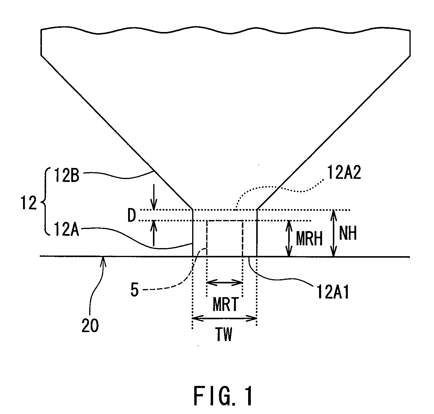
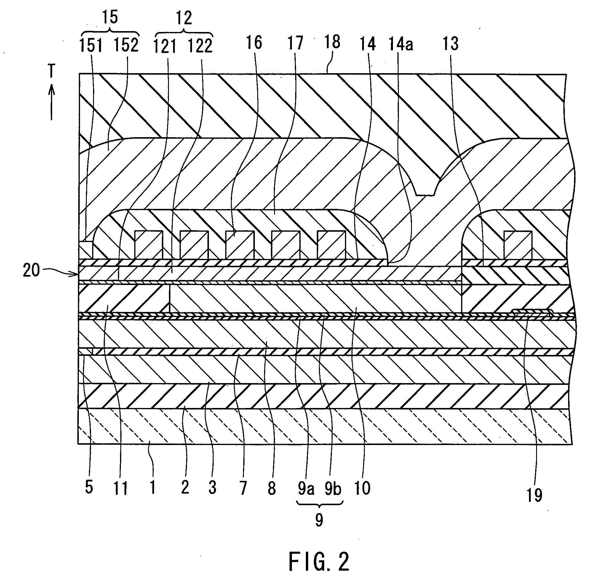
[0048]Preferred embodiments of the invention will now be described in detail with reference to the accompanying drawings. Reference is now made to FIG. 2 and FIG. 3 to describe the configuration of a magnetic head manufactured through a manufacturing method of a first embodiment of the invention. Here is given an example of a magnetic head for the perpendicular magnetic recording system wherein a TMR element is employed as the MR element. FIG. 2 is a cross-sectional view for illustrating the configuration of the magnetic head. FIG. 3 is a front view of the medium facing surface of the magnetic head. FIG. 2 illustrates a cross section orthogonal to the medium facing surface and the top surface of a substrate. The arrow indicated with T in FIG. 2 shows the direction of travel of a recording medium.

[0049]As shown in FIG. 2, the magnetic head of the embodiment has a medium facing surface 20 that faces toward a recording medium. As shown in FIG. 2 and FIG. 3, the magnetic head incorporat...

second embodiment

[0118]Reference is now made to FIG. 20 and FIG. 21 to describe a method of manufacturing a magnetic head of a second embodiment of the invention. Reference is first made to FIG. 20 to describe the substructure 100 of the second embodiment. FIG. 20 is a view for illustrating part of the substructure 100 of the embodiment. The substructure 100 of the second embodiment incorporates a plurality of detection elements 105 each having a film configuration the same as that of the MR film 5P. Since each of the detection elements 105 has the same film configuration as that of the MR film 5P, each of the detection elements 105 has a resistance-area product the same as that of the MR film 5P. Each of the detection elements 105 may have a shape the same as that of the MR film 5P or different from that of the MR film 5P. The detection elements 105 may be disposed in the pre-head portions 101, or may be disposed to extend across the inside and the outside of the pre-head portions 101. FIG. 20 illu...


PUM

PropertyMeasurementUnit
Magnetic fieldaaaaaaaaaa
Electrical resistanceaaaaaaaaaa
Magnetizationaaaaaaaaaa

Abstract

A method of manufacturing a magnetic head includes the steps of: fabricating a substructure in which pre-head portions are aligned in a plurality of rows by forming components of a plurality of magnetic heads on a single substrate; and fabricating the plurality of magnetic heads by separating the pre-head portions from one another through cutting the substructure. In the step of fabricating the substructure, the resistance of an MR film that will be formed into an MR element by undergoing lapping later is detected to determine the target position of the boundary between a track width defining portion and a wide portion of a pole layer based on the resistance thus obtained, and the pole layer is thereby formed. In the step of fabricating the magnetic heads, the surface formed by cutting the substructure is lapped such that the MR film is lapped and the resistance thereof thereby reaches a predetermined value.

Description

BACKGROUND OF THE INVENTION[0001]1. Field of the Invention[0002]The present invention relates to a method of manufacturing a magnetic head used for writing data on a recording medium and reading data stored on the recording medium.[0003]2. Description of the Related Art[0004]For magnetic read / write devices such as magnetic disk drives, higher recording density has been constantly required to achieve a higher storage capacity and smaller dimensions. Typically, magnetic heads used in magnetic read / write devices are those having a structure in which a reproducing (read) head having a magnetoresistive element (that may be hereinafter called an MR element) for reading and a recording (write) head having an induction-type electromagnetic transducer for writing are stacked on a substrate.[0005]For read heads, GMR (giant magnetoresistive) elements utilizing a giant magnetoresistive effect have been practically used as MR elements. Conventional GMR elements have a current-in-plane (CIP) stru...

Claims


Application Information

Patent Timeline
IPC IPC(8): G11B5/127
CPCG11B5/3116G11B5/3166G11B5/3169G11B5/3173G11B5/3967Y10T29/49041Y10T29/49043
Inventor KAGAMI, TAKEOSASAKI, TETSUROWATABE, YUICHISAKAMOTO, TAKAMITSU
Owner TDK CORPARATION
Why Eureka
Eureka Blog
Learn More