Integrated fixing frame for a solar energy module

Inactive Publication Date: 2008-09-18
JIN HSIN HO MOLD ENTERPRISE
View PDF7 Cites 7 Cited by
  • Summary
  • Abstract
  • Description
  • Claims
  • Application Information

AI Technical Summary

Benefits of technology

[0009]The primary object of the present invention is providing an integrated fixing frame for a solar energy module, particularly for an aluminum alloy solar energy module, comprising: a frame body having a plurality of assembling frames which comprise a first sideboard, a second sideboard and an inner board; wherein, a curving rib is installed in between the first sideboard and second sideboard, and a locking chute is defined in between the second sideboard and the inner board which provides a solar panel to insert into the locking chute. Relying upon the curving rib stated above, the assembling frame is able to resist the external forces efficiently, as well as the locking chute of the assembling frame which enables the solar panel to be fixed more stably. In addition, the frame body is made of a high strength aluminum alloy which also ensures the stability and high force resistance.

Problems solved by technology

1. Poor stability: The solar panel is fixed in the U-shape chute, and therefore there a minor interstice exists between the panel and the chute, resulting in instability.
2. Poor force resistance: The supporting board is fixed into the frame via a welding method, and thus when the frame is under stress, of either pulling forces or pressing forces, the supporting board will be broken at the welding points as a result of weakness in those areas.

Method used


Image

  • Integrated fixing frame for a solar energy module
  • Integrated fixing frame for a solar energy module
  • Integrated fixing frame for a solar energy module

Examples


Embodiment Construction

[0017]While this invention is capable of embodiment in many different forms, shown in the drawings and herein described in detail is the preferred embodiment of the invention. The preferred embodiment is disclosed with the understanding that the present description is but one example of the principles of the invention and is not intended to limit the broad aspects of the invention to the single embodiment illustrated.

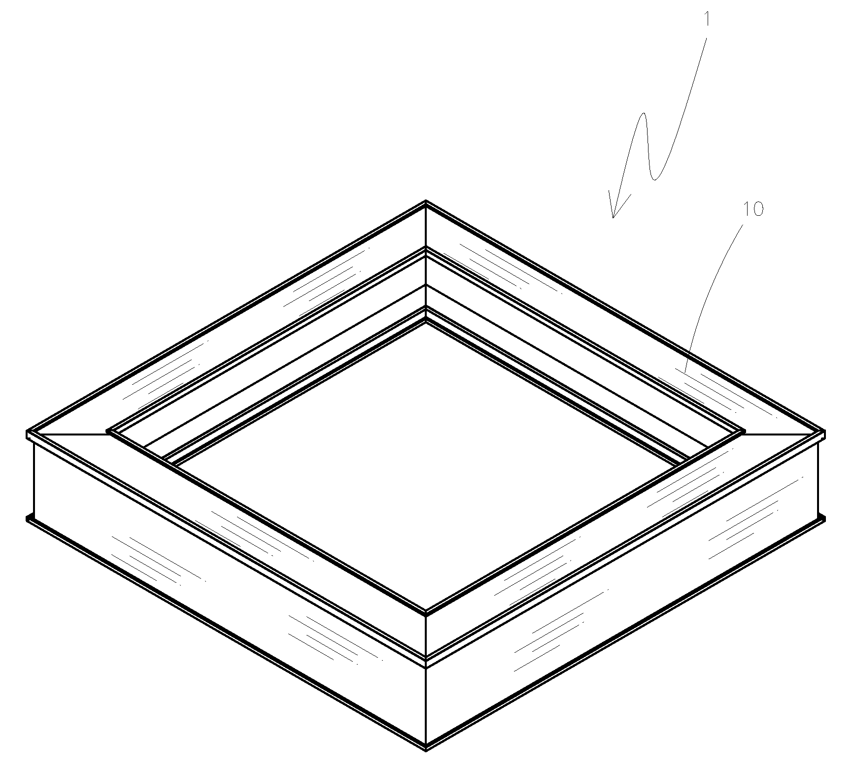
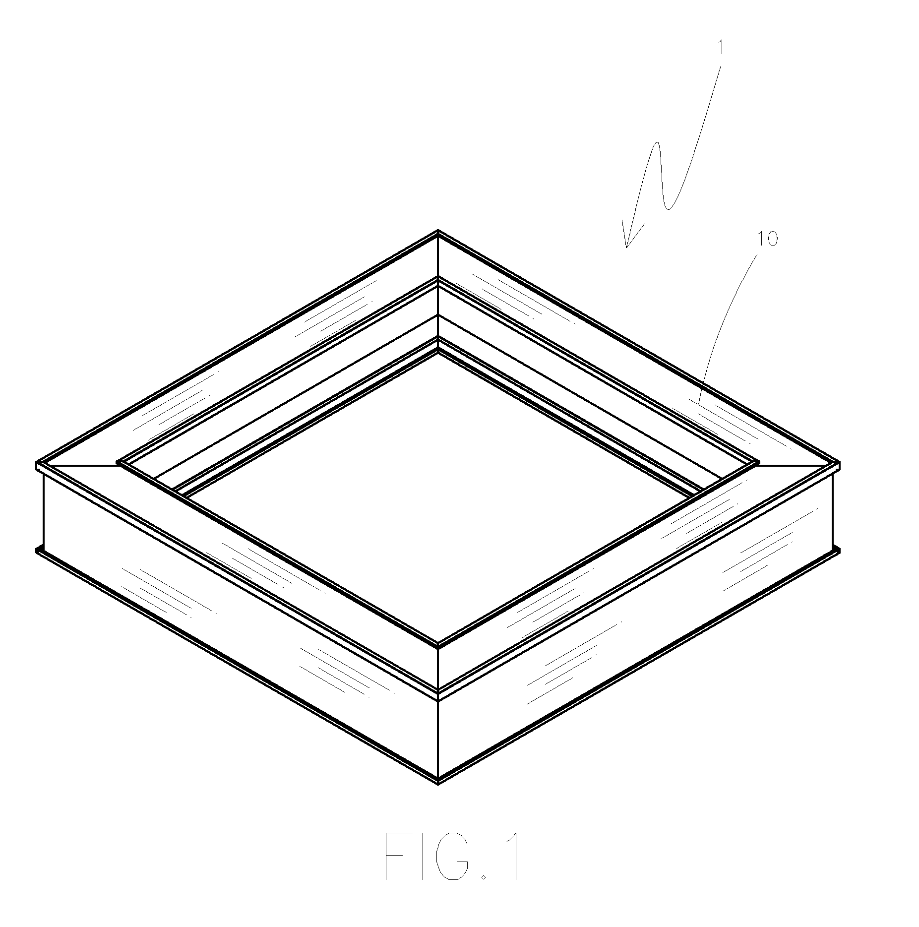
[0018]FIGS. 1 to 3 are perspective, segmented perspective and sectional views schematically showing a fixing frame for a solar energy module of the present invention.

[0019]The frame comprises:

[0020]a frame body 1 having a plurality of assembling frames 10;

[0021]a plurality of assembling frames 10, each of them further comprises a first sideboard 11 and a second sideboard 12. Between the first sideboard 11 and the second sideboard 12, an inner board 13 is installed closing to the second sideboard 12. A curving rib 14 is installed in between the first sideboard 11 and the...


PUM


Abstract

An integrated fixing frame for a solar energy module includes a frame body having a plurality of assembling frames which comprise a first sideboard, a second sideboard and an inner board. Wherein a curving rib is installed in between the first sideboard and second sideboard, and a locking chute is defined in between the second sideboard and the inner board. Relying upon the curving rib stated above, the assembling frame is able to resist the external forces efficiently, as well as the locking chute of the assembling frame which enables the solar panel to be fixed more stably, so that the fixing stability and the high external forces resistance can be achieved.

Description

[0001]The present invention is a continuation-in-part of U.S. application Ser. No. 11 / 686,374, filed on Mar. 15, 2007, and is herein incorporated in its entirety by reference for all purposes.BACKGROUND OF THE INVENTION[0002]1. Field of the Invention[0003]The present invention relates to a fixing frame for a solar energy module. More particularly, the present invention relates to a frame that securely holds a solar panel.[0004]2. Description of Related Art[0005]A conventional fixing frame for a solar module as shown in FIG. 5 and FIG. 6 comprises a frame 30 having a supporting board 31 welded into place; a U-shaped chute 32 is located in the lower portion of the frame 30 and allows a solar panel 20 to be inserted into the chute 32 and fixed in the chute 32. Although the aforesaid frame accomplishes the function of fixing the solar module, it still has some improvable defects, such as:[0006]1. Poor stability: The solar panel is fixed in the U-shape chute, and therefore there a minor ...

Claims


Application Information

Patent Timeline
IPC IPC(8): E04D13/18
CPCF24J2/5211F24J2002/4656H02S20/00Y02E10/50Y02E10/47F24S25/20F24S2080/09H02S30/10
Inventor LEE, CHANG CHI
Owner JIN HSIN HO MOLD ENTERPRISE
Why Eureka
Try Eureka