Backing metal fixture and external wall constructing structure using the same

a technology of backing metal fixtures and constructing structures, applied in the direction of walls, washing machines, mechanical equipment, etc., can solve the problems of achieve the effects of preventing deformation, and preventing uneven surface of external walls to be produced

Active Publication Date: 2008-09-18
NICHIHA CORP
View PDF28 Cites 42 Cited by
  • Summary
  • Abstract
  • Description
  • Claims
  • Application Information

AI Technical Summary

Benefits of technology

[0026]According to the backing metal fixture and the external wall constructing structure of the present invention, the backing metal fixture is prevented from deformation when a securing metal fitting disposed on a butting flat plate portion is fixed to a skeleton (building framework) with a screw, since the backing metal fixture has a reinforcing second leg type near the opening erected rearward from the butting flat plate portion. That is, a pressure applied to the backing metal fixture from screwing the screw can be allocated not only to the first leg unit but also to the reinforcing second leg unit, which can prevent the legs and / or butting flat plate portion from deformation. This likely leads to preventing an unevenness in terms of relative positional relationship between many of the being-used butting flat plate portions of the backing metal fixtures and results in preventing an uneven surface of the external wall to be produced by the securing of the metal fitting. Consequently a securing of the external wall can be stabilized.

Problems solved by technology

This likely leads to an unevenness in terms of a relative positional relationship between many of the mounted butting flat plate portions 61 of backing metal fixtures 6 and results in an uneven surface of the external wall 5.

Method used


Image

  • Backing metal fixture and external wall constructing structure using the same
  • Backing metal fixture and external wall constructing structure using the same
  • Backing metal fixture and external wall constructing structure using the same

Examples


example 1

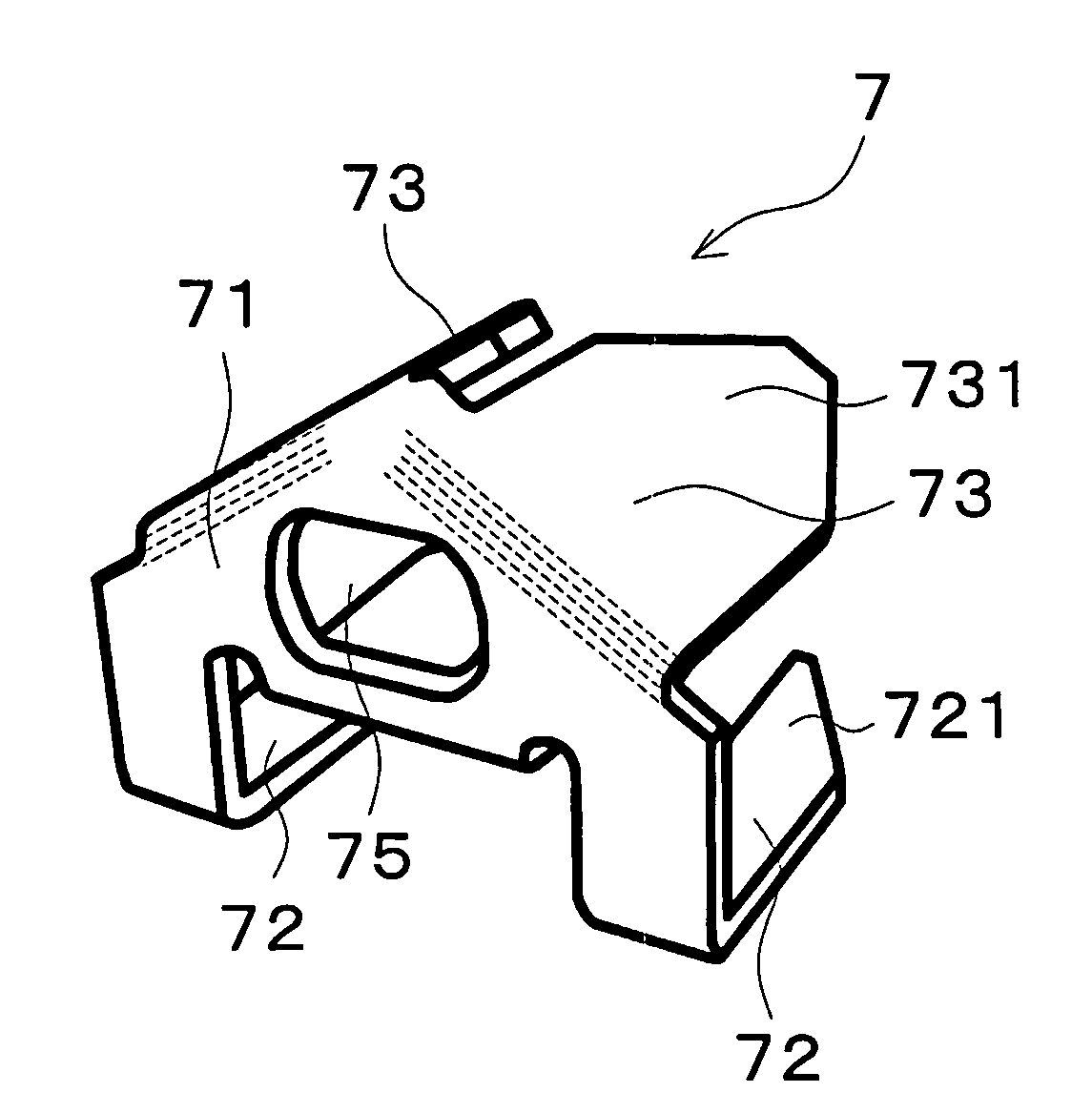
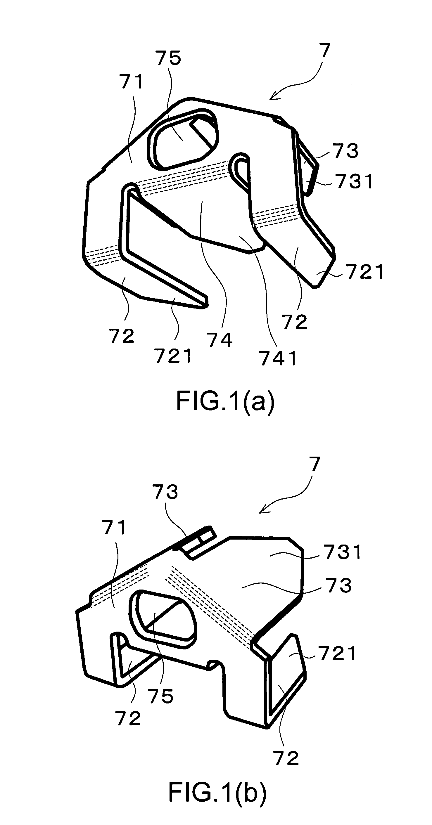
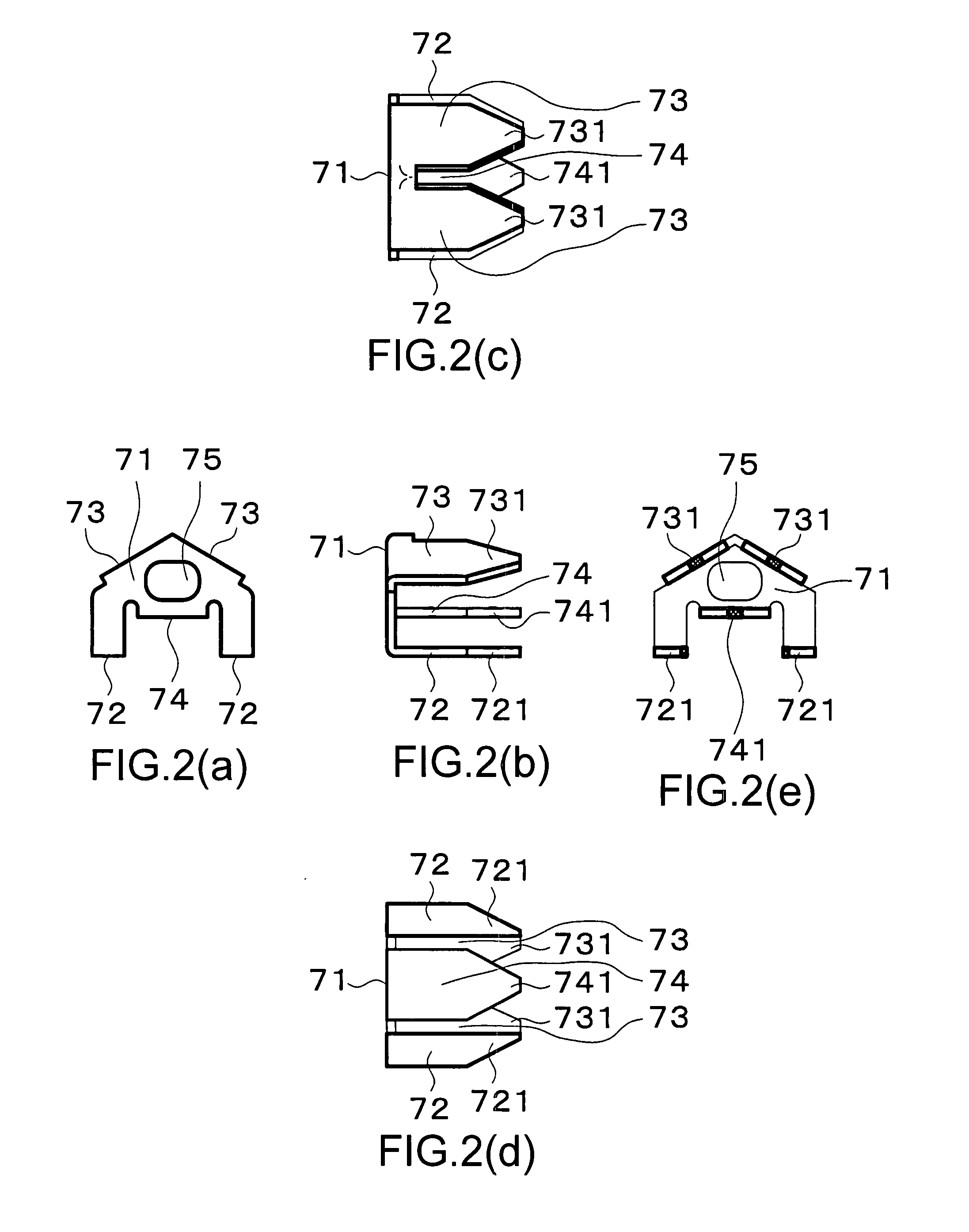
[0042]As shown in FIG. 1, a backing metal fixture 7 of example 1 of the present invention comprises a butting flat plate portion 71, legs 72, 72 of a first leg unit erected rearward from the butting flat plate portion 71, legs 73, 73, 74 of a reinforcing second leg unit and an opening. The butting flat plate portion 71 has an opening 75 to allow a screw 11 (described later) to go through, and three legs 73, 73, 74 of the reinforcing second leg unit stand respectively at three points near the opening 75.

[0043]The backing metal fixture 7 is formed by cutting and bending a 1.2 mm thick steel plate. The opening 75 formed in the butting flat plate portion 71 has an oval shape and the size is sufficiently larger than a diameter of the screw 11.

[0044]Each of the legs 73, 73, 74 of second leg unit is located near the oval opening 75. On the periphery of the opening 75, end distance and edge distance of more than thickness of the steel plate are kept, and the three legs 73, 73, 74 are bent a...

example 2

[0060]Example 2 of the present invention is shown in FIG. 8(a)-FIG. 8(e). This backing metal fixture 7 comprises a butting flat plate portion 71, legs 72, 72 of first leg unit erected rearward from the butting flat plate portion 71, a reinforcing tubular (roughly in the shape of hollow cylinder) leg 73 of a second leg unit, and an opening 75. The butting flat plate portion 71 has the opening to allow a screw 11 to go through and single reinforcing tubular leg 73 standing so that a wall of the tubular leg 73 closely surrounds the opening 75 inside. A rear end portion of the tubular leg 73 is formed of two tapered end portions 731, 731.

[0061]This backing metal fixture 7 is formed by cutting and bending 1.2 mm thick steel plate to form a butting flat plate portion 71 and other parts, and then joining a reinforcing tubular leg 73 of the second leg unit to a rear surface of the butting flat plate portion 71 to form an integrated fixture by press working, welding or brazing. The opening 7...

example 3

[0065]FIGS. 10(a)-10(b) show example 3 of the present invention. A backing metal fixture 7 comprises a butting flat plate portion 71, legs 72, 72 of the first leg unit erected rearward from the butting flat plate portion 71, legs 73, 73 of the reinforcing second leg unit and an opening. The butting flat plate portion 71 has an opening 75 to allow a screw 11 to go through, and two legs 73, 73 of the reinforcing second leg unit erected respectively from two positions near the opening 75.

[0066]The backing metal fixture 7 is prepared by cutting and bending a 1.2 mm thick steel plate to form a pair of legs 73, 73 of a reinforcing second leg unit each of which is made of curved plate to make a part of a hollow cylinder. The opening 75 formed in the butting flat plate portion 71 has a circular shape and the size is sufficiently larger than a diameter of the screw 11.

[0067]Legs 73, 73 of the second leg unit are arranged close to the circular opening 75. On the periphery of the opening 75, t...


PUM


Abstract

The present invention provides a backing metal fixture which is excellent in constructability and stability with fixing an external wall, and an external wall constructing structure using the backing metal fixture. A backing metal fixture used for fixing an external wall to a skeleton via a securing metal fitting and a heat insulating material placed on a front surface of the skeleton, comprising: a butting flat plate portion to be butted against a rear surface of the securing metal fitting having an opening in the center area to allow a fixing member to go through, and a first leg unit and a second leg unit erected rearward from the butting flat plate portion, wherein the second leg unit is erected from a position closer to the opening than the first leg unit.

Description

BACKGROUND OF THE INVENTION [0001]1. Field of Technology[0002]The present invention relates to a backing metal fixture and an external wall constructing structure using the backing metal fixture. The fixing base unit used for fixing an external wall to an external wall substrate comprises a skeleton and a heat insulating material such as a plastic foam fixed to the skeleton.[0003]2. Description of the Related Arts[0004]A constructing structure shown in FIG. 13 and FIG. 14 has been known as shown in JP2007-046345A. FIG. 13 and FIG. 14 show an external wall constructing structure 1 with external heat insulation where an insulating material 3 made of plastic foam is fixed to a front surface 21 of a skeleton 2, a backing metal fixture 6 is pressed into the insulating material 3 so that a front surface of the backing metal fixture 6 and a front surface 31 of the insulating material 3 are almost aligned, and then a securing metal fitting 4 with a rear surface 41 is butted against the fron...

Claims


Application Information

Patent Timeline
Patent Type & Authority Applications(United States)
IPC IPC(8): E04B2/00
CPCE04B1/7637F16B43/00E04F13/0833E04B1/7629E04F13/0832
Inventor HIKAI, SATOSHITAKAMI, SHIN
Owner NICHIHA CORP
Why Eureka
Try Eureka