
Ice maker equipped with a convection fan

a convection fan and ice maker technology, applied in the field of ice makers equipped with convection fans, can solve the problems of increasing electric power consumption and lack of space, and achieve the effects of accelerating cooling speed, accelerating ice making speed, and maximizing space and electric power

Inactive Publication Date: 2008-09-18
ZIPPY TECH
View PDF9 Cites 12 Cited by
  • Summary
  • Abstract
  • Description
  • Claims
  • Application Information

AI Technical Summary

Benefits of technology

[0003]In view of the aforesaid problems occurred to the prior ice making techniques, the primary object of the present invention is to provide an improved ice maker to better utilize limited space and electric power and provide a desired ice making environment with a low and even temperature to accelerate ice making speed. The ice maker of the invention not only can speed up cooling and does not occupy a lot of space and improves efficiency.
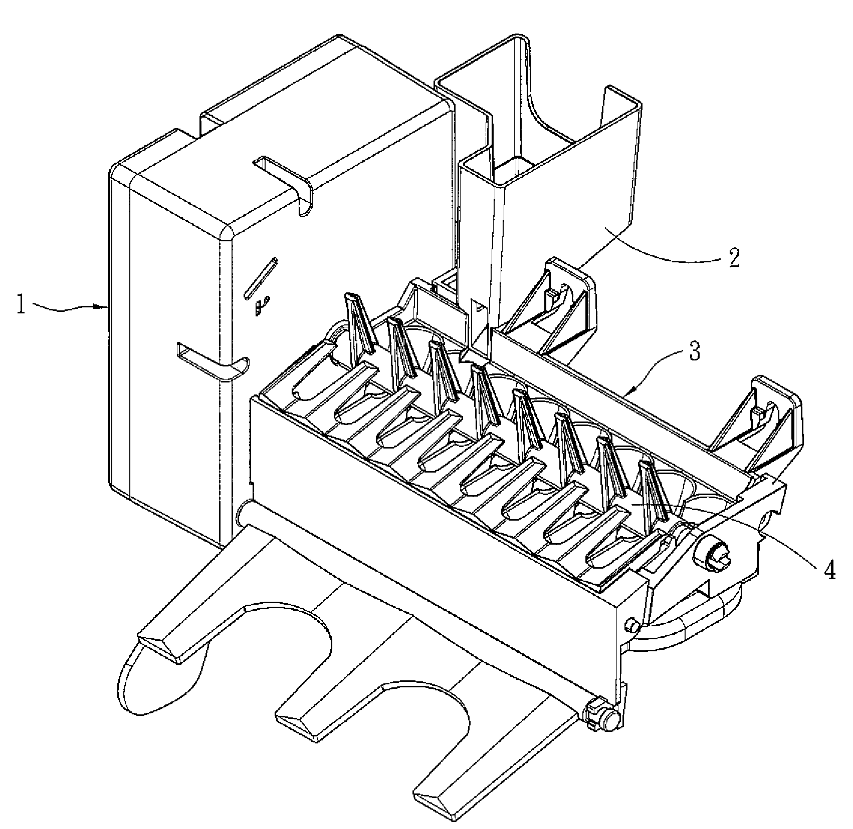
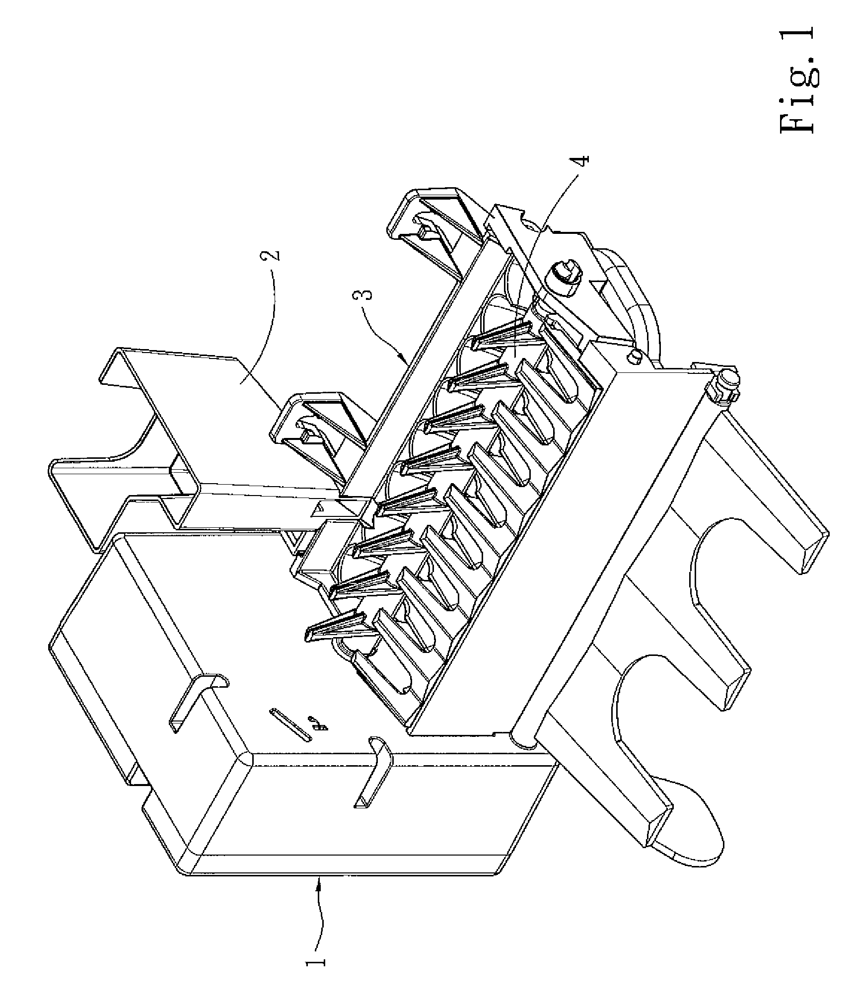
[0004]The present invention provides an ice maker equipped with a convection fan. It includes an ice making tray, a water intake unit, an ice sweeping shaft and a control box. The control box has at least one convection fan and at least one air inlet and at least one air outlet to allow the convection fan to generate convection of cooling air. The air outlet directs airflow to the ice making tray so that the cooling air blows areas of the ice making tray where temperature drops at a slower speed. Thereby overall temperature dropping speed can be accelerated to improve ice making efficiency.

Problems solved by technology

Trying to further speed up the cooling effect encounters many problems such as lack of space or increasing electric power consumption.

Method used


Image

  • Ice maker equipped with a convection fan
  • Ice maker equipped with a convection fan
  • Ice maker equipped with a convection fan

Examples


Embodiment Construction

[0011]Please refer to FIG. 1, the ice maker equipped with a convection fan according to the invention includes a convection fan 5. It is installed at a low temperature environment to automatically receive water and freeze the water to become ice cubes 8 (referring to FIG. 4B). Then the ice cubes 8 are automatically removed to resume the ice making process. It includes an ice making tray 3, a water intake unit 2, an ice sweeping shaft 4 and a control box 1. The water intake unit 2 directs clean water to the ice making tray 3. The water is frozen to become the ice cubes 8. Then the ice sweeping shaft 4 is rotated to remove the ice cubes 8 outside the ice making tray 3. The control box 1 controls operation procedures of the water intake unit 2 and ice sweeping shaft 4 to produce ice.

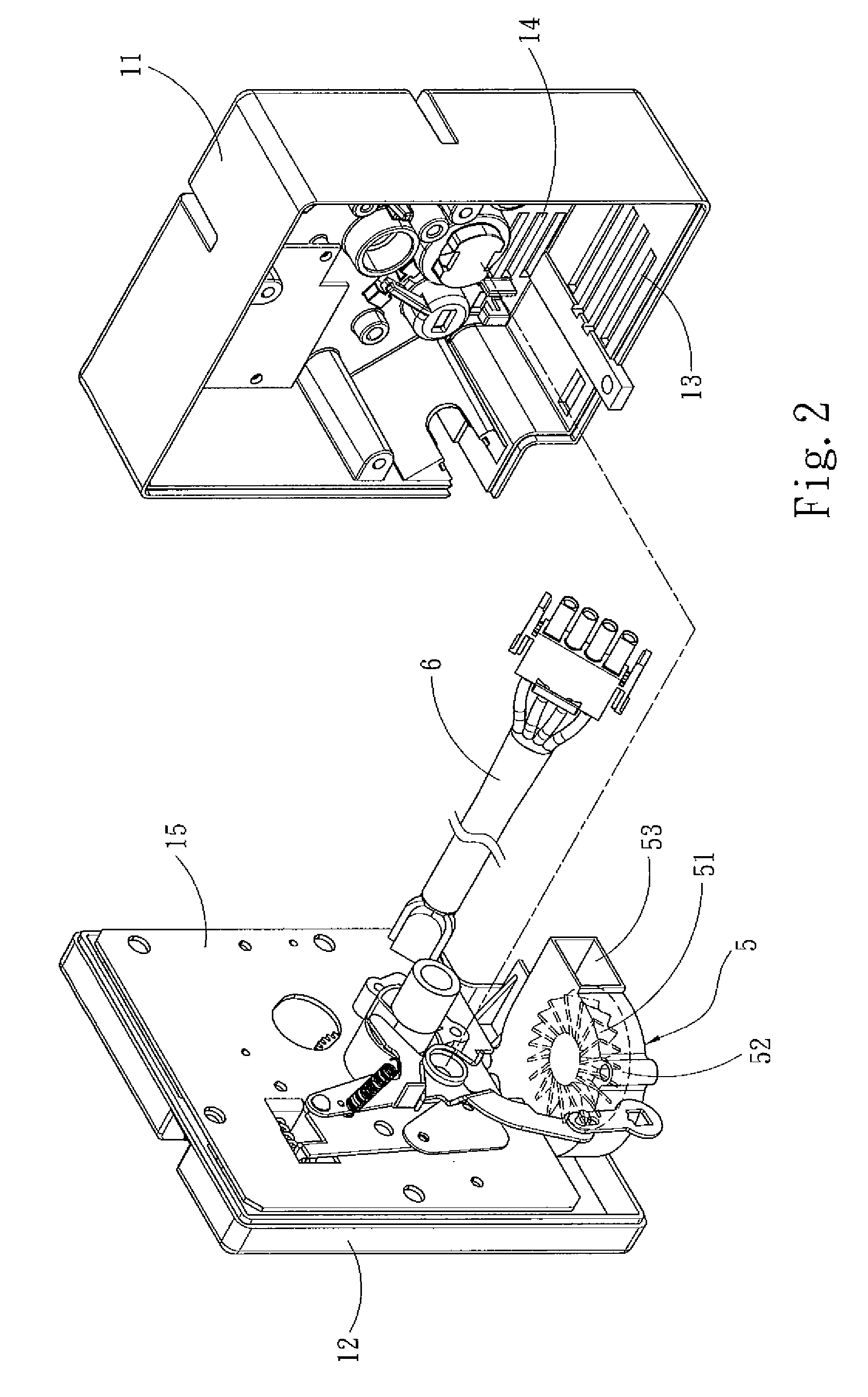
[0012]Referring to FIG. 2, the control box 1 includes a front lid 11, a rear lid 12, a control unit 15, a power cord 6 and the convection fan 5. The front lid 11 and rear lid 12 are coupled together to enca...


PUM


Abstract

An ice maker equipped with a convection fan includes a control box, an ice making tray, a water intake unit and an ice sweeping shaft. The control box holds at least one convection fan and has at least one air inlet and one air outlet to allow the convection fan to generate cooling air convection to accelerate cooling speed and improve ice making efficiency.

Description

FIELD OF THE INVENTION[0001]The present invention relates to an ice maker equipped with a convection fan that has at least one air fan system to speed up cooling airflow to accelerate ice making speed.BACKGROUND OF THE INVENTION[0002]Ice cubes are frequently being added to people's drinks or used for various cooling purposes A wide variety of ice makers have been developed and marketed. Many of them focus on faster ice making speed and automation to enable users to get the ice cubes whenever needed. R.O.C. patent publication No. 330978 entitled “Automatic ice making apparatus and freezer” includes a water supply trough, an ice making tray and a water supply pump. The water supply rough is located in a freezer at a desired position and built with an improved structure, and a control procedure is provided for the automatic ice making apparatus. Another R.O.C. patent publication No. 396264 entitled “Ice making control apparatus for thermoelectric modular refrigerators” has a main heat ...

Claims


Application Information

Patent Timeline
Patent Type & Authority Applications(United States)
IPC IPC(8): F25C5/18
CPCF25C1/04F25D2317/0681F25D2317/061F25C2400/10F25C2305/024
Inventor HSU, SHIH-HSIEN
Owner ZIPPY TECH
Learn More