
Flow cell, flow cell manufacturing method and particle measurement instrument

a technology of flow cell and manufacturing method, applied in the direction of manufacturing tools, instruments, material electrochemical variables, etc., can solve the problems of 0.7 mpa sample pressure in practical use, and the method cannot be applied in principle to the measurement of particles under liquid phase, phase or superphas

Inactive Publication Date: 2008-09-18
RION COMPANY
View PDF11 Cites 15 Cited by
  • Summary
  • Abstract
  • Description
  • Claims
  • Application Information

AI Technical Summary

Benefits of technology

[0010]It is therefore an object of the present invention to solve the problems as seen in the prior art and to provide a flow cell which can introduce a sample under high pressure into a measuring device, a method for manufacturing the flow cell, and a particle measuring instrument using the flow cell.

Problems solved by technology

However, a limit of the sample pressure which is in practical use is 0.7 MPa due to withstand pressure limitations and the flow cell.
However, this method cannot be applied in principle to the measurement of particles under a liquid phase, a reactive gas phase or a super critical phase because the sample mixes with an existing media (normally, air) within the chamber.
Further, a mechanism with a nozzle may be complicated and it is also difficult to obtain withstand pressure performance above 1 MPa.
Referring to the method for measuring the particles by reducing the pressure using the regulator, disturbance such as dusting by the regulator is caused.

Method used


Image

  • Flow cell, flow cell manufacturing method and particle measurement instrument
  • Flow cell, flow cell manufacturing method and particle measurement instrument
  • Flow cell, flow cell manufacturing method and particle measurement instrument

Examples


first embodiment

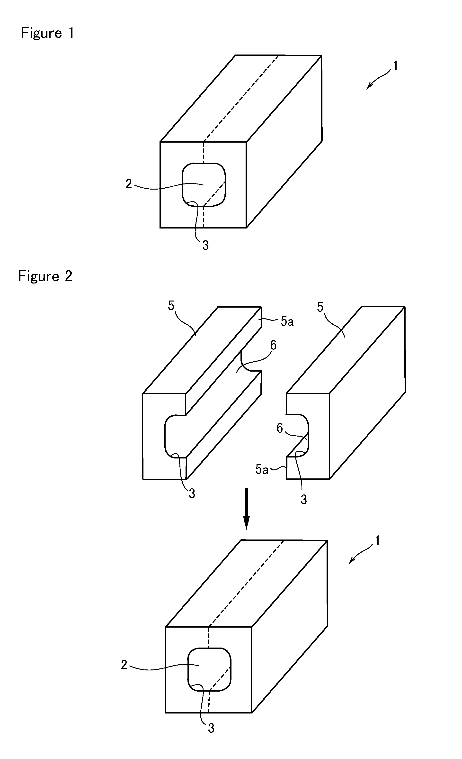
[0026]As shown in FIG. 1, a flow cell 1 of a first embodiment is provided with a flow channel 2 of which the cross section is formed in a substantially quadrangular shape and which has four (4) rounded corners 3.

[0027]A method for manufacturing the flow cell 1 is shown in FIG. 2. A groove 6 of which the cross section is a quadrangle and which has two (2) rounded corners 3 (for example, R=0.1) is first formed on the largest surface 5a of a block 5 made of quartz which is a transparent material (groove forming process). Next, a wall surface of the groove 6 and the surface 5a are optically polished to provide a desired accuracy (polishing process). Two blocks 5 provided with such a groove 6 are made. The size of block 5 which is a rectangular parallelepiped is, for example, 10 mm×5 mm×30 mm, the width of the groove 6 is 0.5 mm, and the depth thereof is 0.25 mm.

[0028]Next, two blocks 5, each provided with the groove 6, are disposed so that the surfaces 5a and the grooves 6 face each oth...

second embodiment

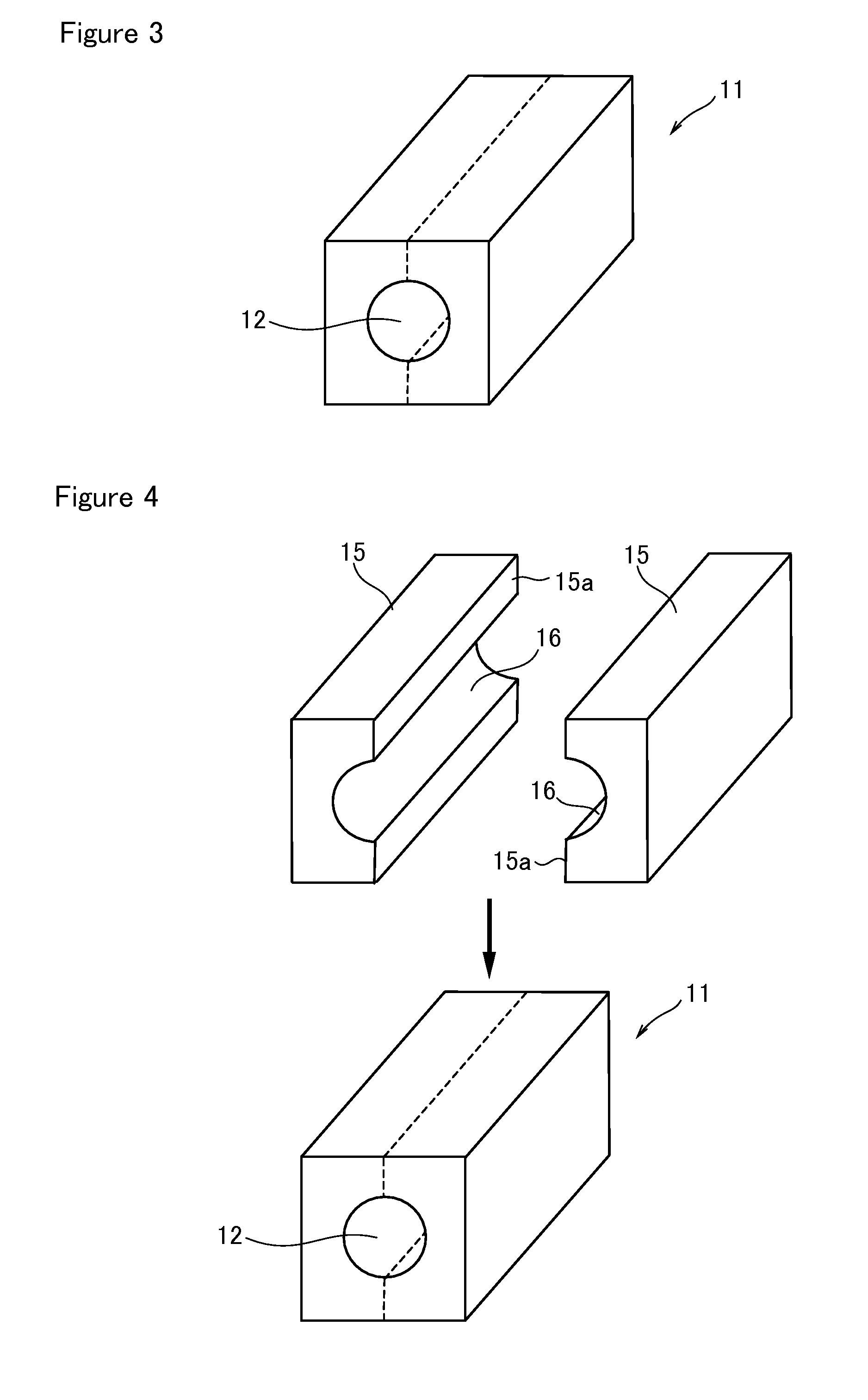
[0030]FIG. 3 shows a flow cell 11 of a second embodiment, in which a flow channel 12 is formed of a circular shape in section.

[0031]A method for manufacturing the flow cell 11 is shown in FIG. 4. First, a groove 16 of a semicircular shape in section is formed on the largest surface 15a of a block 15 made of quartz which is a transparent material (groove forming process). Next, the wall surface of the groove 16 and the surface 15a are optically polished to provide a desired accuracy (polishing process). Two blocks 15, each provided with such a groove 16, are made. The size of block 15 which is a rectangular parallelepiped is, for example, 10 mm×5 mm×30 mm. The groove 16 is formed of a semicircular shape in section, of which the radius is 0.25 mm.

[0032]Next, two blocks 15, each provided with the groove 16, are disposed so that the surfaces 15a and the grooves 16 face each other and the widths of the grooves 16 agree, wherein the two surfaces 15a are joined by welding to provide the fl...


PUM

PropertyMeasurementUnit
pressureaaaaaaaaaa
pressureaaaaaaaaaa
depthaaaaaaaaaa

Abstract

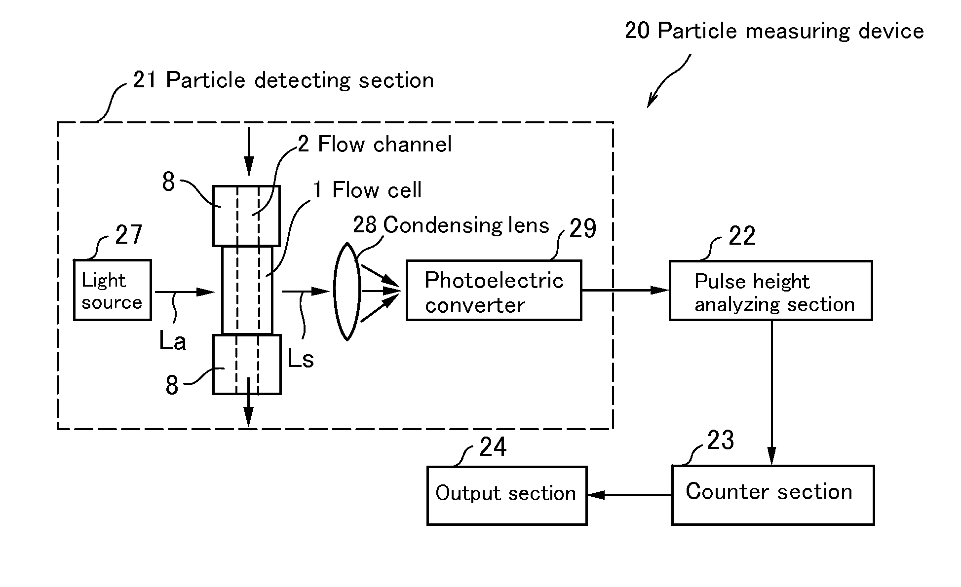
A flow cell 1 is provided with a flow channel 2 which has rounded corners 3 in section. A measuring sample under high pressure is introduced into the flow channel 2 formed in the flow cell 1 and particles existing in the measuring sample are measured. The measuring sample is in a liquid phase, a gaseous phase or a super critical phase above 1 MPa.

Description

BACKGROUND OF THE INVENTION[0001]1. Field of the Invention[0002]The present invention relates to a flow cell for introducing a sample under high pressure into a measuring instrument, a method for manufacturing the flow cell, and a particle measuring instrument using the flow cell.[0003]2. Description of the Prior Art[0004]A high pressure fluid is used in a material gas used in a production process for an electronic device, compressor air for a machine driven jet gun and the like. A liquid phase, a gaseous phase, and a super critical phase exist in the high pressure fluid. In particular, in the case of the high pressure fluid used in the production process for the electronic device such as a semiconductor, it is required to control small particles contained in the fluid. Under the present circumstances, it is possible to measure the particles up to a pressure of 0.7 MPa using a fine particle measuring instrument which is available in the marketplace. In the case of high pressure gas,...

Claims


Application Information

Patent Timeline
Patent Type & Authority Applications(United States)
IPC IPC(8): G01N15/02G01N27/26B29C65/00
CPCG01N15/1404G01N2021/0346G01N21/05G01N21/0317
Inventor KONDO, KAORUSUGAWARA, HIROSHIFUTATSUKI, TAKASHISUZUKI, AKIRATATSUMI, MASAHIKOOGURA, KOUKIWATANABE, JUNICHI
Owner RION COMPANY
Learn More