Flow cytometer

a flow cytometer and flow cytometer technology, applied in the field of flow cytometers, can solve the problems of large footprint of laser apparatus per se, and large accompanying peripheral devices, and achieve the effect of analyzing the fluorescence of targets more appropriately and efficiently

Active Publication Date: 2009-01-13
NIHON KOHDEN CORP
View PDF24 Cites 64 Cited by
  • Summary
  • Abstract
  • Description
  • Claims
  • Application Information

AI Technical Summary

Benefits of technology

[0010]It is therefore an object of the invention to provide a flow cytometer which is capable of analyzing especially fluorescence of a target particle more appropriately and efficiently.
[0017]a first filter, disposed between the flow cell and the third detector and adapted to eliminate scattered light generated from the target particles by the irradiation of the first light beam.
[0018]With the above configuration, since an inexpensive conventional laser light source may be used for exciting the forward scattered light and the orthogonal scattered light, an inexpensive flow cytometer can be obtained. In addition, since the light source for exciting the fluorescence is individually provided, the analysis for the fluorescence of the target particles can be reliably and efficiently performed.
[0033]With this configuration, the sensitivity and the S / N ratio of the fluorescence detection can be enhanced.
[0040]With the above configurations, stray light can be efficiently eliminated, thereby further enhancing the sensitivity and the S / N ratio of the fluorescence detection.

Problems solved by technology

However, an argon laser is expensive.
In addition, not only is the footprint of the laser apparatus per se large, but also accompanying peripheral devices, such as a required power source for driving the laser, and the like, are also large.
Furthermore, overall power consumption by the argon laser is also large.
The operations to perform such changing are considerably complicated.
However, of a flow cytometer, a light source and peripheral equipment thereof are expensive.
Accordingly, installation of a flow cytometer for each type of the target particles involves enormous installation cost and an enormous footprint, which is economically disadvantageous.

Method used


Image

  • Flow cytometer
  • Flow cytometer
  • Flow cytometer

Examples


first embodiment

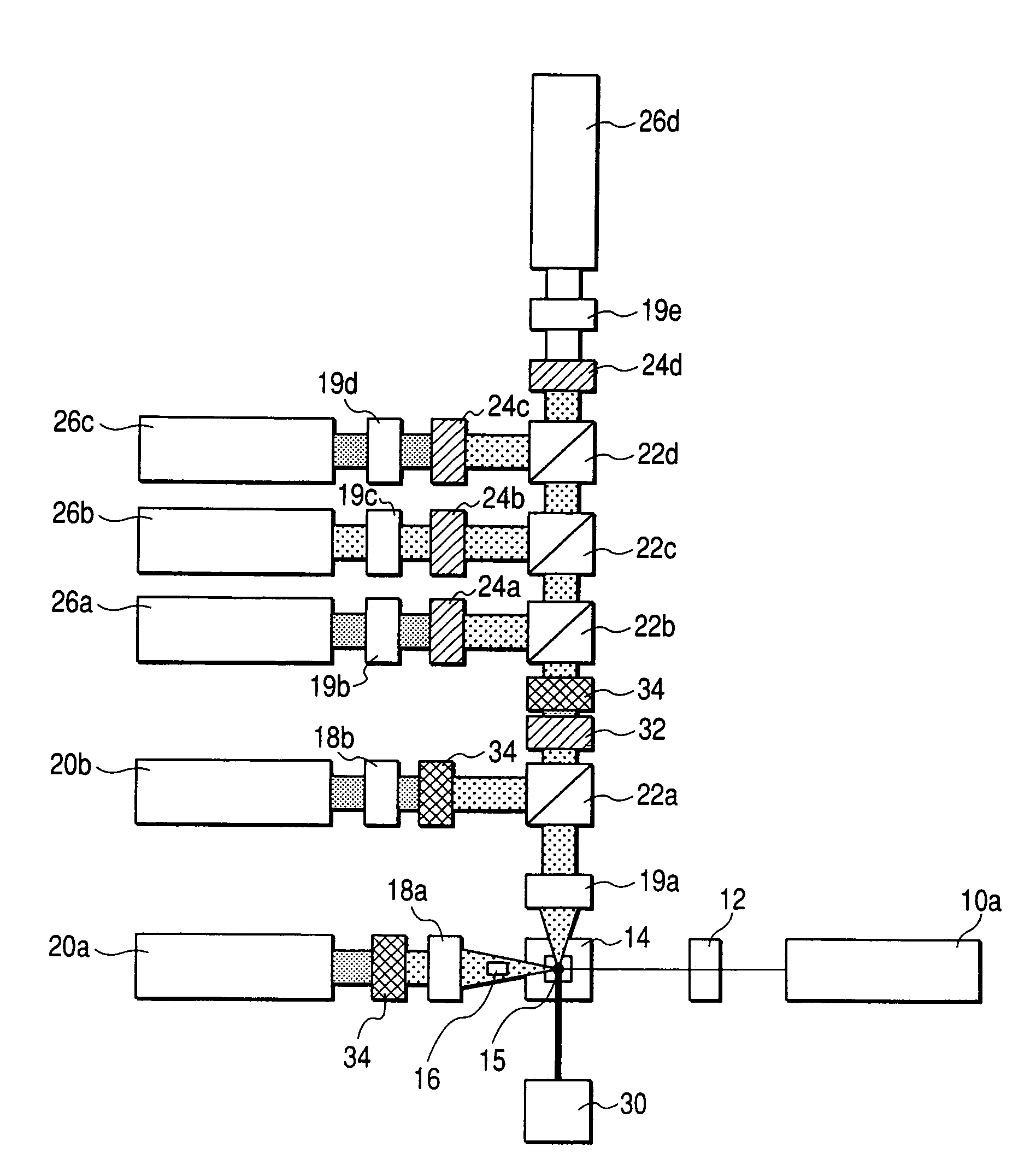
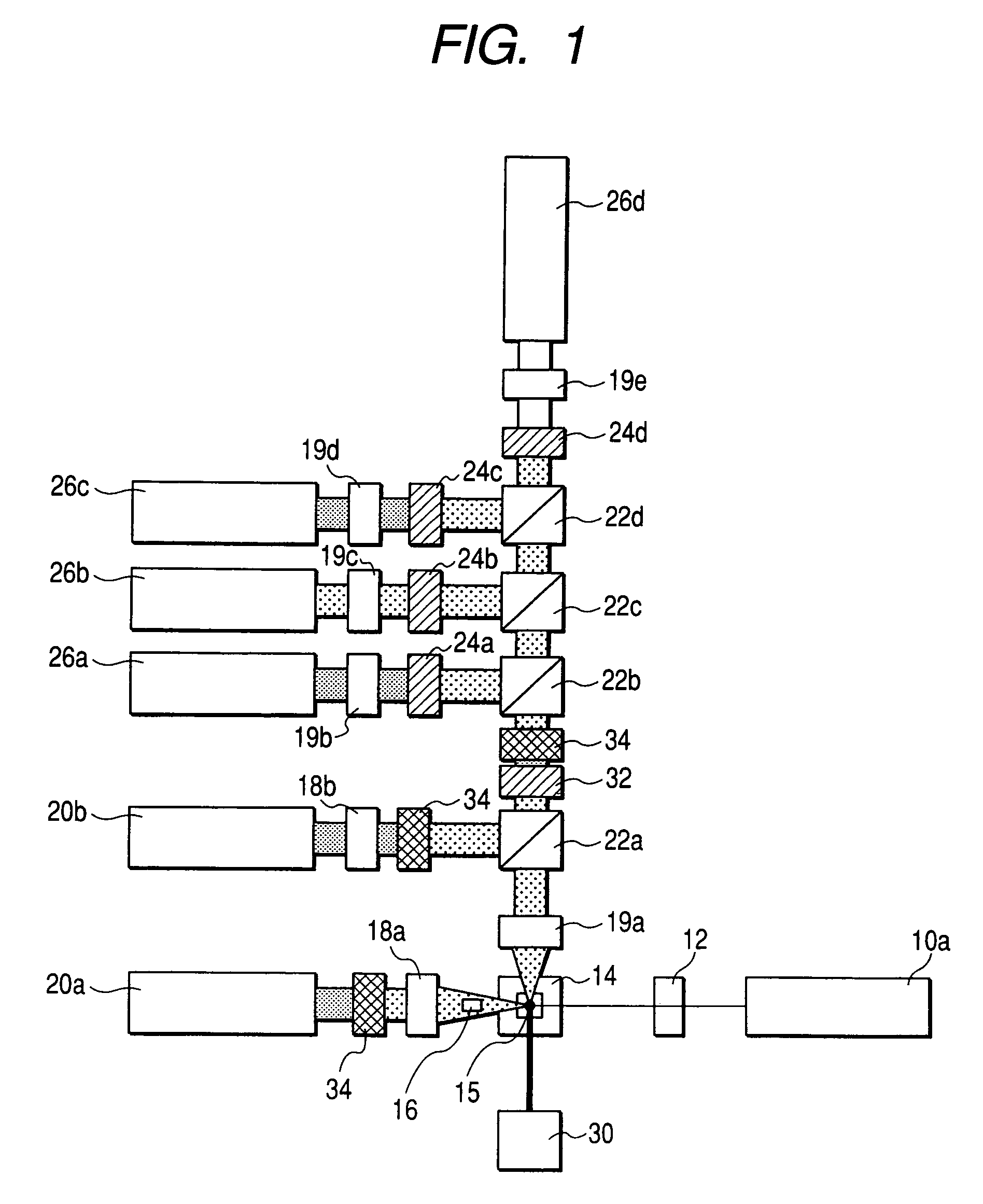
[0059]FIG. 1 shows a flow cytometer according to the invention. A laser light source 10a serves as a light source for scattered light excitation and irradiates the target particle 15 in the flow cell 14 with a laser beam by way of the beam shaping lens 12. Thus, the laser beam radiated at the target particle 15 excites forward scattered light and orthogonal scattered light respectively. Meanwhile, the flow cytometer is configured such that a laser beam directly incident on the flow cell 14 is blocked by a shade 16 disposed in front of the flow cell 14.

[0060]In this embodiment, as a light source for exciting fluorescence with respect to the target particle, a light-emitting diode (LED) 30 which can emit light in the blue-light region of relatively shorter wavelength is disposed. A light beam emitted from the LED 30 irradiates the target particle 15 in the flow cell 14, thereby exciting fluorescence.

[0061]Forward scattered light thus having been excited by the target particle 15 is co...

third embodiment

[0070]Next, the invention will be described. A composite lens is obtained by integrating a plurality of lens elements having different focal points so as to form a single circular lens (cf., Japanese Patent Publication No. 11-23447A). It is possible to easily enhance sensitivity and S / N ratio in fluorescence detection by disposing such a composite lens on an optical path of scattered light, and appropriately disposing a plurality of fluorescence detectors at focal positions of the respective lens elements constituting the composite lens.

[0071]FIG. 4 shows one example of such a configuration. Components similar to those in the first embodiment will be designated by the same reference numerals and repetitive explanations for those will be omitted. In this embodiment, composite lenses 40, 42a, and 42′ are respectively applied to the forward scattered light detector 20a, the orthogonal scattered light detector 20b, and the fluorescence detectors 26a to 26c. More specifically, the conden...


PUM

PropertyMeasurementUnit
spectrum widthaaaaaaaaaa
fluorescenceaaaaaaaaaa
wavelengthaaaaaaaaaa

Abstract

A laser light source emits a first light beam irradiating a solution including target particles and being flowed in a flow cell to generate forward scattered light and orthogonal scattered light therefrom. A light emitting diode emits a second light beam irradiating the solution in the flow cell to generate at least one wavelength of fluorescence therefrom. A first detector is adapted to detect the forward scattered light. A second detector is adapted to detect the orthogonal scattered light. At least one third detector is adapted to detect the at least one fluorescence. A first filter is disposed between the flow cell and the third detector and adapted to eliminate scattered light generated from the target particles by the irradiation of the first light beam.

Description

BACKGROUND OF THE INVENTION[0001]The invention relates to a flow cytometer which radiates a laser beam toward a flow of aqueous solution containing cells, chromosomes, and biopolymers included therein, thereby detecting fluorescence and scattered light radiated from the cells or the like, to thus classify and count the number of the same.[0002]Flow cytometers have been in wide use: (1) for measuring relative amounts, between cells, of DNA, RNA, enzyme, protein, and the like; (2) for examining functions, such as cell activity, antibody productivity, and enzyme activity; and (3) for automatically classifying types of cells, chromosomes, lymphocytes, or the like.[0003]A conventional example of a flow cytometer of this type has the following configuration. A sample solution is prepared by, for instance, diluting and staining a blood sample. The sample solution is supplied in a form of a narrow flow to a center section of a flow cell. The narrow flow is irradiated with narrowly-converged...

Claims


Application Information

Patent Timeline
Patent Type & Authority Patents(United States)
IPC IPC(8): G01N21/00G01N15/14G01N21/05G01N21/51G01N21/64
CPCG01N15/147G01N21/05G01N21/51G01N21/645G01J3/0208G01N15/1434G01N2021/6421G01N2021/6467G01N2021/6482
Inventor NAGAI, YUTAKA
Owner NIHON KOHDEN CORP
Why Eureka
Try Eureka