Instrument and method for optical particle sensing

a technology of optical particle and instrument, applied in the direction of instruments, material analysis, biological material analysis, etc., can solve the problem of limited size of biological particles that can be analyzed using currently available technology

Active Publication Date: 2014-08-21
INVITROX
View PDF4 Cites 58 Cited by
  • Summary
  • Abstract
  • Description
  • Claims
  • Application Information

AI Technical Summary

Benefits of technology

[0032]In one embodiment, the microparticles have a particle size in the range of between about 0.1 and 10 μm, and ideally have a relatively consistent amount of active agent bound to them. One way to produce particles with a relatively consistent amount of active agent bound to them is to use dendrimers, where the dendrimers include a known quantity of the active agent. Another way is to produce polymer particles with a) a relatively narrow size distribution, and b) a relatively consistent amount of protected functional groups, so that after the polymers are produced, the protecting groups can be removed, and the functional groups used to conjugate the polymer particles to an active agent.

Problems solved by technology

The size of biological particles that can be analyzed using currently available technology is limited.

Method used


Image

  • Instrument and method for optical particle sensing
  • Instrument and method for optical particle sensing
  • Instrument and method for optical particle sensing

Examples


example 1

Representative Focused Light Scattering Device

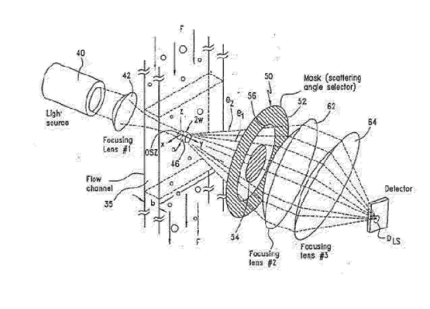
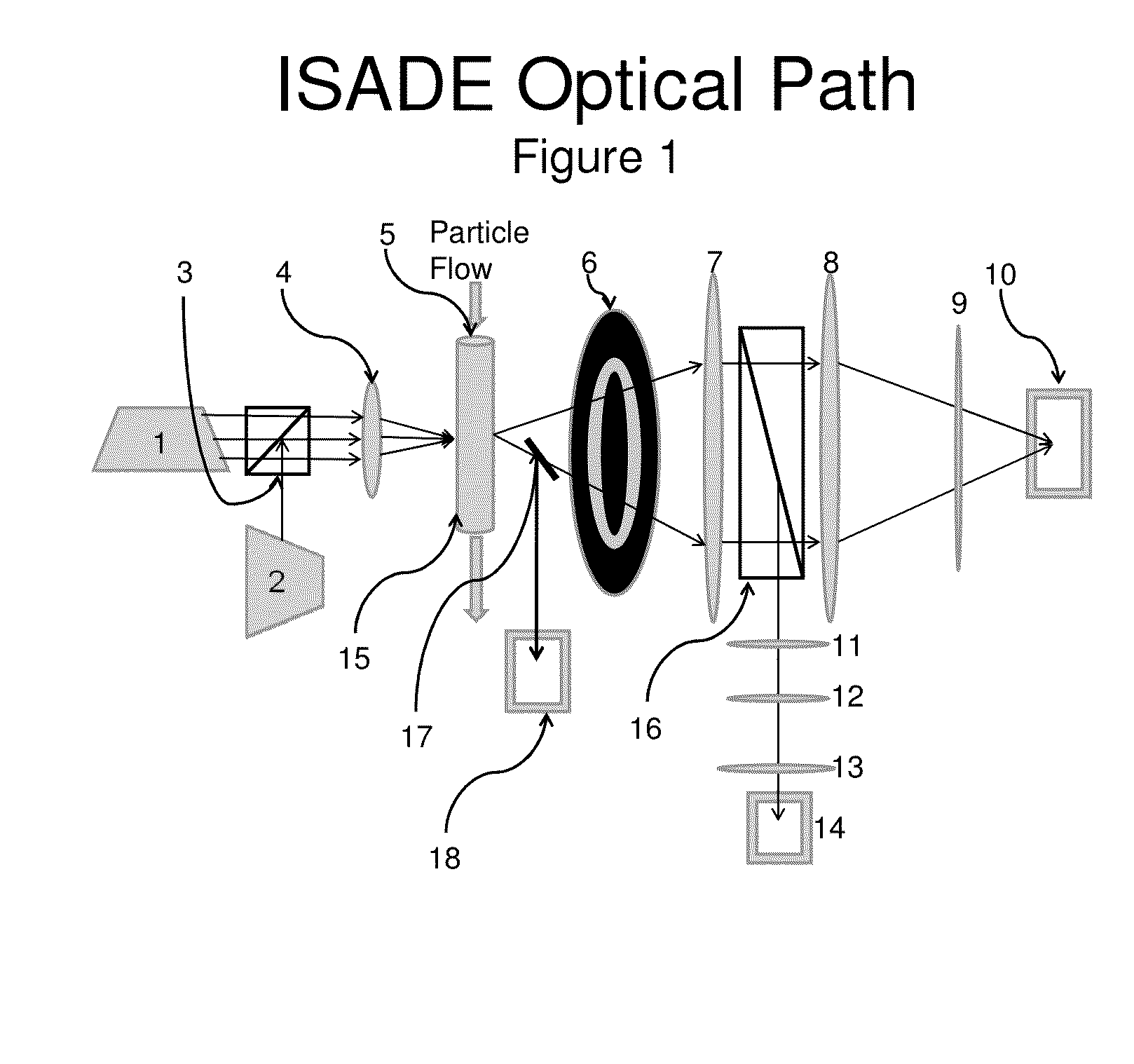
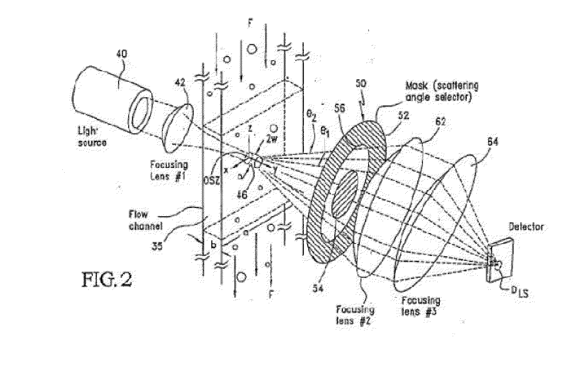
[0334]A representative focused light scattering device is shown in FIG. 1. A first laser (1) emits light at a first wavelength, and a second laser (2) emits light at a second wavelength. Both beams of light pass through a first beam splitter (3) and through a first focusing lens (4) before they enter into a flow cell (15). The flow cell includes a site (5) for hydrodynamic injection of the sample. As the platelets in the flow cell pass through the beams of light, the light is scattered as it hits the platelets. The scattered light passes through a circular spatial filter (6) and then through a first collimating lens (7). The light beam passes through a second beam splitter (16), which splits the light into two beams. A first beam passes through a second focusing lens (8) and through a first chromatic filter (9) that passes scattered light from the first laser (1) through a first detector (10). The second beam passes through a second coll...

example 2

Detection of Microparticle's (MP) Present in a Biological Sample

[0337]In this example, a specimen is subject to particle sizing and counting. After an appropriate dilution of the sample, the diluted specimen is introduced into the device for analysis. As counting proceeds, counts will accumulate in the size region less that 1 micron. The appearance of MP in this size region will indicate the presence of MPs.

example 3

Microparticle Characterization

[0338]Once MPs are detected, as described in Example 2, it may be important to determine the source of the MP (from platelets neutrophils, tumor cell, etc.). This Example provides two different options for characterizing the MP.

[0339]The first option is to use MP sizing and counts. In this case, the specimen is incubated with a second particle with a specific ligand conjugated to its surface. The choice of the ligand will depend on the specific MP be characterized. For example, if the MP of interest has coagulation tissue factor (TF) on its surface, the conjugated particle can be conjugated with an antibody against TF-particle or with coagulation factor FVII. Either ligand will specifically bind to MPs with TF on their surfaces.

[0340]When the conjugated particles are incubated with the anti-TF conjugated particles, a new size corresponding to the TF-MP+anti-TF-particles will appear when the MP and the probe particle are counted. In a like manner, other ...


PUM

PropertyMeasurementUnit
widthaaaaaaaaaa
widthaaaaaaaaaa
sizeaaaaaaaaaa

Abstract

Devices for detecting particle sizes and distributions using focused light scattering techniques, by passing a sample through a focused beam of light, are disclosed. In one embodiment, the devices include one or more lasers, whose light is focused into a narrow beam and into a flow cell, and dispersions are passed through the flow cell using hydrodynamic sample injection. In another embodiment, a plurality of lasers is used, optionally with hydrodynamic sample injection. Particles pass through and scatter the light. The scattered light is then detected using scatter and extinction detectors, and, optionally, fluorescence detectors, and the number and size of the particles is determined. Particles in the size range of 0.1 to 10 μm can be measured. Using the device, significantly smaller particles can be detected than if techniques such as EQELS, flow cytometry, and other conventional devices for measuring biological particles.

Description

FIELD OF THE INVENTION[0001]This application is generally in the area of single particle optical light scattering devices, and techniques for using them, particularly measure extremely small particles.BACKGROUND OF THE INVENTION[0002]It is often essential to characterize biological particles by their size, surface condition, states of activation of any surface receptors, distribution, and the like. This information is useful in cell-based assays and other processes that rely upon those characteristics. Additionally, it is useful in certain diagnostic applications to detect known changes of the surface of a biological particle. Accordingly, it can be desirable to detect the surface and monitor changes to the surface in an efficient and accurate manner.[0003]“Electrophoretic Quasi-Elastic Light Scattering” (EQELS) is one method for characterizing biological particles. This method uses electrophoresis that is dependent on the particle's surface charge density to identify and characteri...

Claims


Application Information

Patent Timeline
Patent Type & Authority Applications(United States)
IPC IPC(8): G01N15/02G01N33/50
CPCG01N2015/03G01N2015/0073G01N15/1459G01N2015/0065G01N2015/008G01N15/1434G01N2015/1006G01N2015/1087G01N2015/0084G01N2500/10G01N33/5026G01N15/0211G01N33/5044G01N33/502G01N33/483G01N21/6428G01N33/5008
Inventor GABRIEL, DON
Owner INVITROX
Why Eureka
Try Eureka