Thermal Control of a Flow Cell Battery

a flow cell battery and flow cell technology, applied in the direction of secondary cells, cell components, non-aqueous electrolyte cells, etc., can solve the problems of intermittent power availability, damage to the flow battery system, and the ability of redox batteries to be utilized as uninterruptible power supplies

a flow cell battery and flow cell technology, applied in the direction of secondary cells, cell components, non-aqueous electrolyte cells, etc., can solve the problems of intermittent power availability, damage to the flow battery system, and the ability of redox batteries to be utilized as uninterruptible power supplies

US20100092813A1Inactive Publication Date: 2010-04-15IMERGY POWER SYST

Image

  • Thermal Control of a Flow Cell Battery
  • Thermal Control of a Flow Cell Battery
  • Thermal Control of a Flow Cell Battery

Examples


Embodiment Construction

[0024]In the following description, for the purposes of explanation, specific details are set forth in order to provide a thorough understanding of the embodiments of the invention. However, it will be apparent that the invention may be practiced without these specific details.

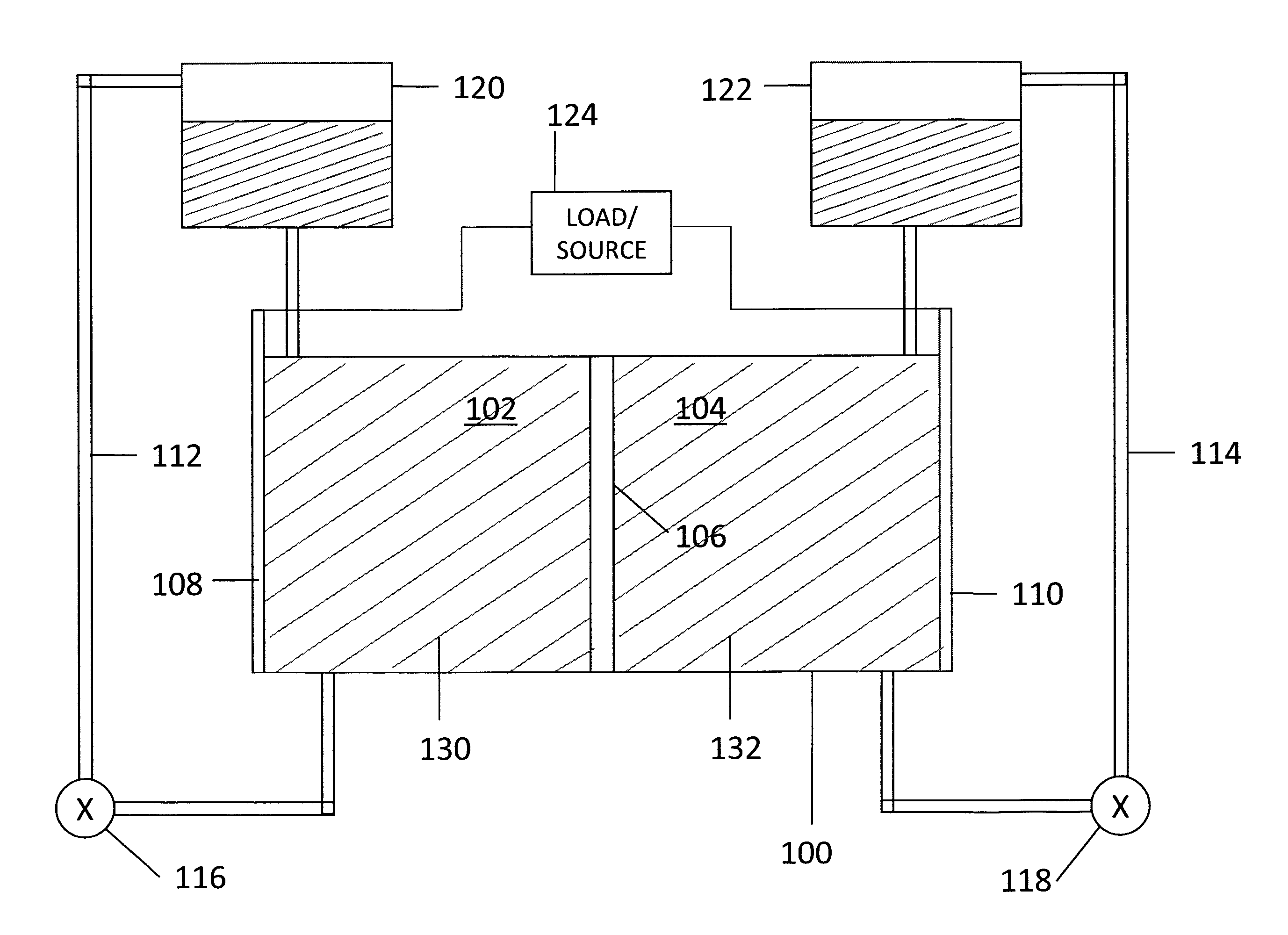
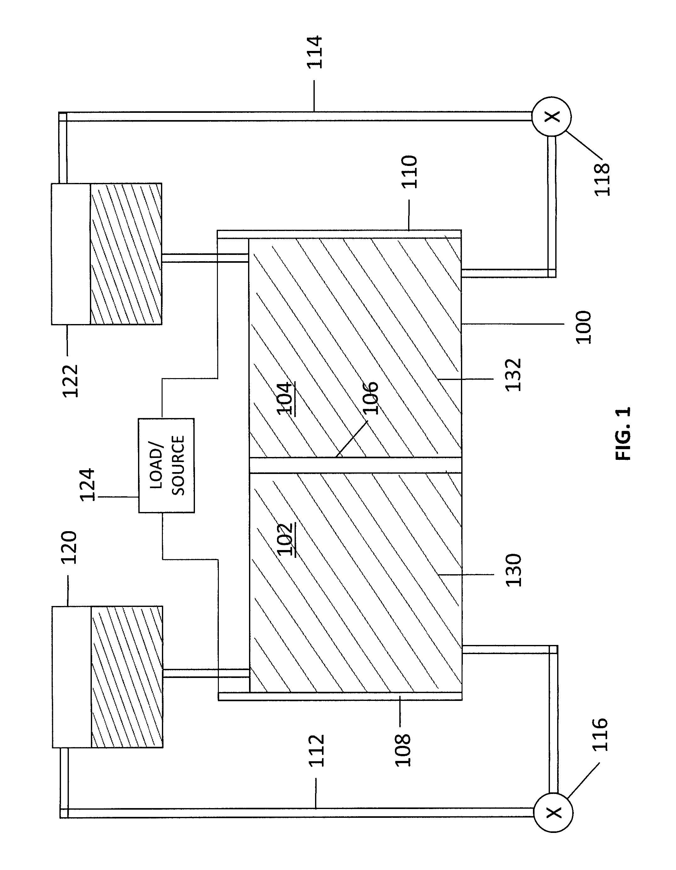
[0025]A reduction-oxidation (redox) flow cell is the minimal component of a redox battery. Multiple flow cells can be coupled (e.g., “stacked”) to form a multi-cell battery. The cell is made up of two half-cells separated by a membrane, through which ions are transferred during a redox reaction. One half-cell contains an anolyte and the other half-cell contains a catholyte, the anolyte and catholyte being collectively referred to as electrolytes. The electrolytes (anolyte and catholyte) are flowed through the half-cells, often with an external pumping system. At least one electrode in each half cell provides a surface on which the redox reaction takes place and from which charge is transferred.

[0026]The redox ...


PUM

PropertyMeasurementUnit
temperaturesaaaaaaaaaa

Abstract

A flow battery with thermal management is presented. The flow battery is housed in an enclosure where fluid is uniformly circulated about holding tanks of electrolyte to control the temperature inside the enclosure.

Description

CROSS-REFERENCE TO RELATED APPLICATIONS[0001]The present application claims benefit under 35 U.S.C. §119(e) of U.S. Provisional Application No. 61 / 104,614 filed on Oct. 10, 2008, entitled “Thermal Control Of A Flow Cell Battery,” the content of which is hereby incorporated by reference in its entirety.BACKGROUND[0002]1. Technical Field[0003]The present invention is related to controlling a flow cell battery and, in particular, to thermal control of a flow cell battery.[0004]2. Discussion of Related Art[0005]Reduction-oxidation (redox) flow batteries store electrical energy in a chemical form, and subsequently dispense the stored energy in an electrical form via a spontaneous reverse redox reaction. A redox flow battery is an electrochemical storage device in which an electrolyte containing one or more dissolved electro-active species flows through a reactor cell where chemical energy is converted to electrical energy. Conversely, the discharged electrolyte can be flowed through a re...

Claims


Application Information

Patent Timeline
15 Apr 2010
Publication
US20100092813A1
IPC
H01M8/04; H01M8/00
CPC
H01M8/0432; H01M8/04701; H01M8/188; H01M10/42; H01M10/5004; Y02E60/528; H01M10/5018; H01M10/5024
Inventors
SAHU, SAROJ KUMAR