
Vehicle in particular a motorcycle and engine/gearbox unit for a vehicle

a technology for motorcycles and gearboxes, applied in the field of vehicles, can solve the problems of large chain sag, large friction loss, and constructive encapsulation of chains, and achieve the effects of improving handling, high progression, and reducing friction loss

Active Publication Date: 2008-09-18
BAYERISCHE MOTOREN WERKE AG
View PDF31 Cites 5 Cited by
  • Summary
  • Abstract
  • Description
  • Claims
  • Application Information

AI Technical Summary

Benefits of technology

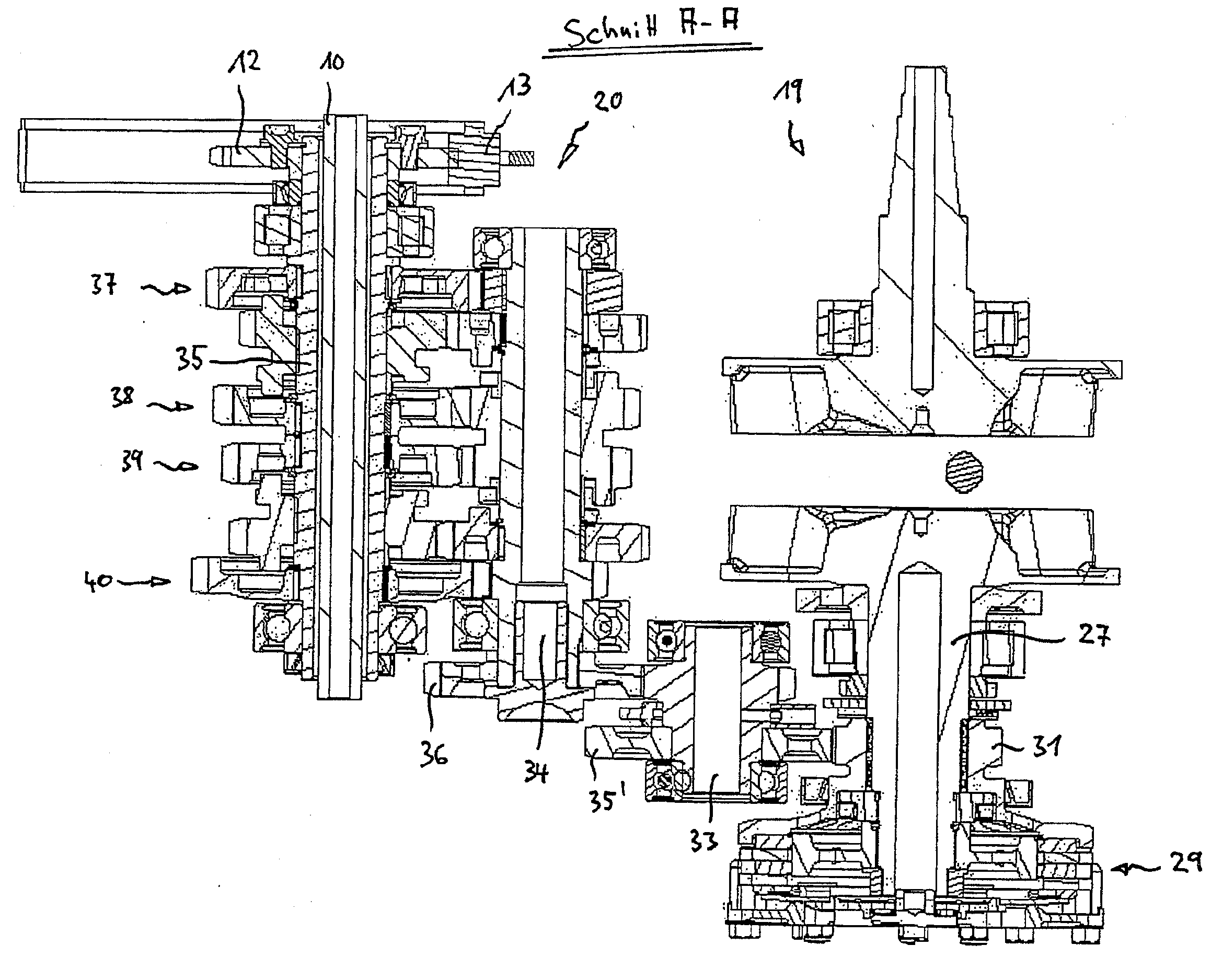
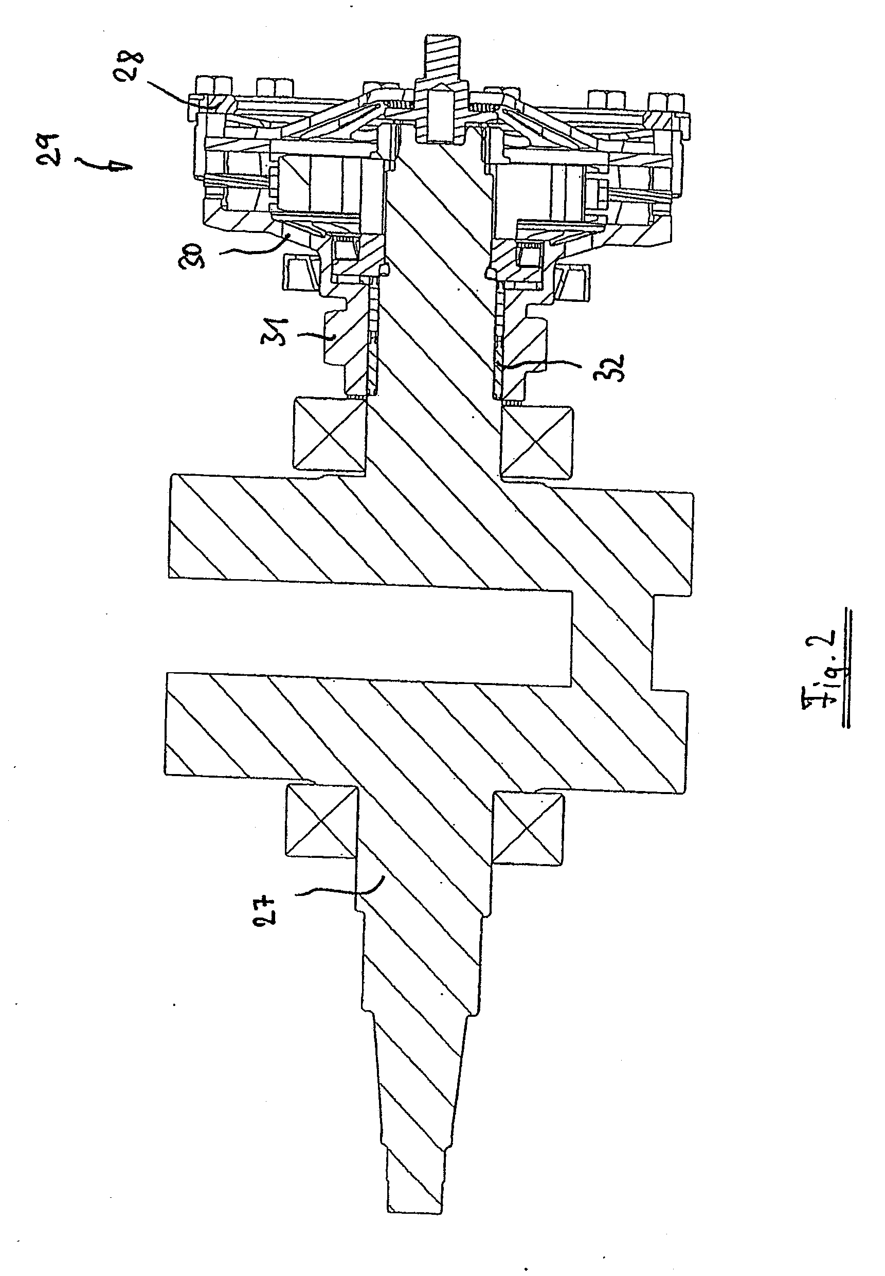
The present invention provides a novel vehicle concept and an engine / transmission unit that allows for a more efficient and compact design. The clutch in the engine / transmission unit is situated coaxially to the crankshaft, which allows for higher speeds and lower torques. This results in a smaller clutch diameter, which in turn avoids interference with the transmission output shaft. The vehicle concept avoids the need for a separate swing arm axis and a separate engine mounting point, which simplifies the construction and reduces costs. The invention also avoids the need for a separate oil bath for the clutch, which can result in rapid contamination of the oil. The chain pinion is also situated coaxially to the swing arm axis, which further simplifies the vehicle design.

Problems solved by technology

A greater chain sag results in relatively strong friction losses and requires a special chain guide.
Greater chain wear also results with a large chain sag.
A further result of the large chain sag may be strong running noises due to “chain whipping.”“Encapsulation” of the chain is constructively complex, in particular in the event of large chain sag.
A further problem of typical motorcycle concepts may be seen in that the pinion diameter is limited in relation to the swing arm mounting by the clearance required for a pivot movement of the swing arm.
Furthermore, it is problematic that the swing arm spar is situated adjacent to or below the driving strand of the chain, which implies a relatively large gauge of the swing arm spars and, in the case of a single-arm swing arm, makes the construction very complex, because the engine housing and the swing arm mounting must also be housed having an offset in relation to the transmission output shaft between the rear wheel and the output shaft of the transmission.
Because in typical motorcycles, the swing arm spars must always lie between the top and bottom chain strands, the bottom spring strut attachment is located at a relatively low level, which in turn has an unfavorable effect on the spring strut progression.
Oil-bath clutches have the disadvantage that they may result in a relatively rapid contamination of the oil.
In normal motorcycles, the frame is also typically designed relatively complexly.
Frame constructions of this type imply an unfavorable force flow and are also relatively heavy and costly to produce.
The engine mounting is also relatively difficult with frames of this type, because the engine and the transmission are “embedded” very tightly in the frame.
This is a relatively cumbersome design and has therefore also not been successful.
However, Stoffregen does not provide a concrete description of how the chain pinion may be driven and how the chain pinion is to be situated in relation to the transmission.
In typical motorcycles, a coaxial configuration of swing arm axis and transmission output pinion would not be possible at all, because the swing arm axis would penetrate the clutch.

Method used


Image

  • Vehicle in particular a motorcycle and engine/gearbox unit for a vehicle
  • Vehicle in particular a motorcycle and engine/gearbox unit for a vehicle
  • Vehicle in particular a motorcycle and engine/gearbox unit for a vehicle

Examples


Embodiment Construction

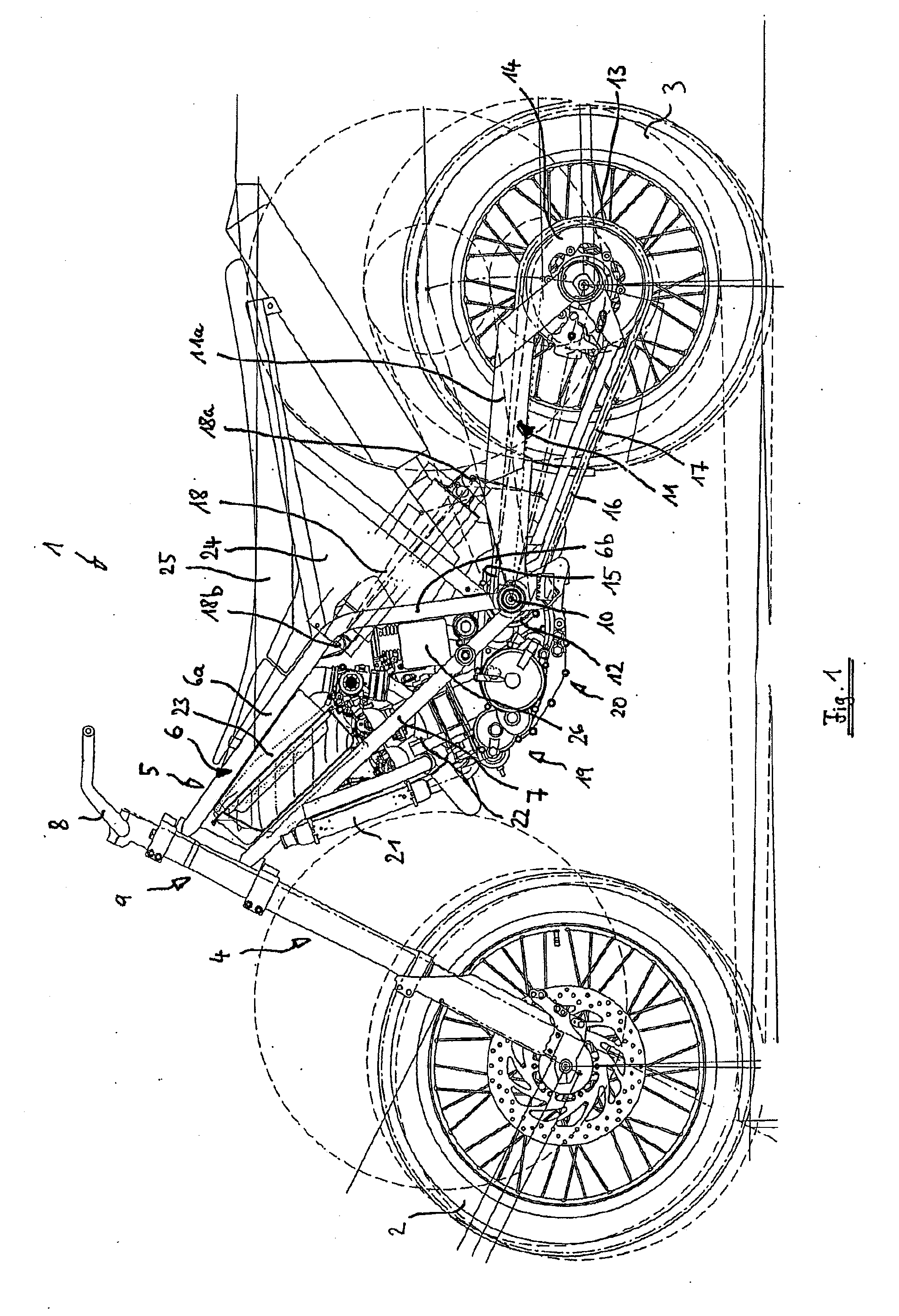
[0058]FIG. 1 shows a motorcycle 1 having a front wheel 2 and a rear wheel 3. The front wheel 2 is connected via a telescoping fork 4 to a frame 5 of the motorcycle 1. In the side view shown in FIG. 1, a top left frame tube 6 and a bottom left frame tube 7 of the frame 5 may be recognized. The top left frame tube 6 may be divided into a forward section 6a and a rear section 6b. The top left frame tube 6 is curved in the transition area between the frame tube sections 6a, 6b. The forward section 6a is essentially linear in the side view shown in FIG. 1. The bottom left frame tube 7 is also essentially linear in the side view shown in FIG. 1. The two frame tubes 6, 7 extend from an area below handlebars 8 from a steering head bearing 9 diagonally downward to the rear. The section 6b of the top left frame tube 6“intersects” the bottom left frame tube 7.

[0059]As may be seen best from FIG. 8, the frame 5 is constructed essentially symmetrically in relation to a middle longitudinal axis of...


PUM


Abstract

A vehicle, in particular a motorcycle, having an engine with a crankshaft extending transversely to a travel or longitudinal direction of the vehicle, a transmission, and a clutch, which may assume an open state and a closed state. The clutch, which allows a torque transmission from the crankshaft to the transmission in the closed state, is situated coaxially to the crankshaft. The engine and transmission may be arranged such that the vehicle's rearswing arm may be located coaxially with an axis of a transmission output shaft.

Description

[0001]This application is a Continuation of PCT / EP2006 / 006478, filed Jul. 4, 2006, and claims the priority of DE 05015290.9, filed Jul. 14, 2005, the disclosures of which are expressly incorporated by reference herein.BACKGROUND AND SUMMARY OF THE INVENTION[0002]The present invention relates to a vehicle, in particular a motorcycle, according to the preamble of claim 1, as well as an engine / transmission unit for a vehicle according to the features of claim 47.[0003]In typical motorcycles having a chain or belt drive, the pinion, which drives the chain or the drive belt, is typically situated at least approximately 65 mm offset in relation to the axis to which the rear wheel swing arm is linked. The clutch is commonly situated on the transmission input shaft in typical motorcycles. Seen in a side view of the motorcycle, the clutch thus “overlaps” the transmission output shaft. In the following, the transmission output shaft is understood as the shaft on which the pinion is situated, ...

Claims


Application Information

Patent Timeline
Patent Type & Authority Applications(United States)
IPC IPC(8): B62M7/02B60K5/04
CPCB62K11/04B62M11/00B62M7/02B62K25/283
Inventor THEOBALD, MARKUS
Owner BAYERISCHE MOTOREN WERKE AG
Learn More