Luminescence measuring apparatus

a technology of light-emitting measuring apparatus and light-emitting area, which is applied in the direction of optical radiation measurement, color/spectral property measurement, instruments, etc., can solve the problem of limited light emission area (light reception area), and achieve the effect of increasing direct light received, decreasing reflection, and decreasing light intensity decay

Inactive Publication Date: 2008-09-18
HITACHI HIGH-TECH CORP
View PDF13 Cites 2 Cited by
  • Summary
  • Abstract
  • Description
  • Claims
  • Application Information

AI Technical Summary

Benefits of technology

[0012]This configuration makes it possible to place the luminescent substance nearest to the detector. This increases the direct light received by the detector while decreasing reflection by the structure provided to support detection components. It is also possible to use such a low-height vessel having an opening on its upper face in which the luminescent-substance-included fluid contained in the vessel is distributed thinly or substantially as widely as the effective area of the detector. This increases the direct light received by the detector while decreasing the decay of light in intensity due to propagation through the fluid and the vessel. In addition, a reflector may be disposed below a transparent vessel so that the light emitted in the opposite direction of the detector is reflected toward the detector.

Problems solved by technology

However, since a sample is contained in a cylindrical test tube, the method

Method used


Image

  • Luminescence measuring apparatus
  • Luminescence measuring apparatus
  • Luminescence measuring apparatus

Examples


first embodiment

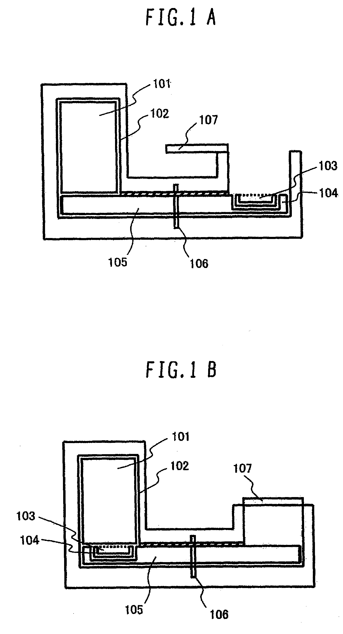
[0020]FIGS. 1A and 1B show a first embodiment of the present invention. In FIG. 1A, measurement is not being performed. In FIG. 1B, measurement is being performed.

[0021]According to the present invention, a detector 101 is installed inside a dark room 102 as shown in FIG. 1A. A fluid 103 including a luminescent substance is contained in a vessel 104. With a cover 107 opened, the vessel 104 is set on a vessel carrier 105 which can be rotated by a rotation axis 106. By a part of the surface of the vessel carrier 105, the detector 101 remains shielded from external light.

[0022]To perform measurement, the cover 107 is closed as shown in FIG. 1B. Then, the rotation axis 106 is spun to rotate the vessel carrier 105 and slides the luminescent-substance-included fluid 103 contained in the vessel 104 set on the vessel carrier 105 until the fluid 103 comes right under the detector 101. Under this condition allowing the detector 101 to receive light only from the luminescent substance, the amo...

second embodiment

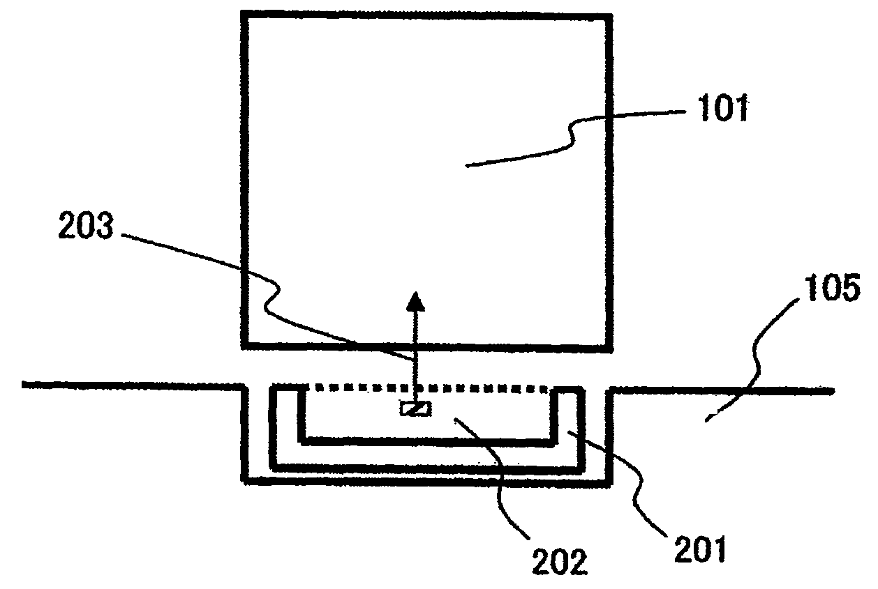
[0023]FIG. 2 illustrates a second embodiment of the present invention. It shows how the opening of the vessel is disposed relative to the detector when measurement is being performed. The detector 101 detects light 203 from a luminescent-substance-included fluid 202 contained in a vessel 201 held by the vessel carrier 105. Since the opening of the vessel 201 faces the detector 101, the light 203 does not propagate through the vessel 201 and therefore does not decay in intensity. The detector 101 shows high measurement sensitivity since such incident light 203 is detected.

third embodiment

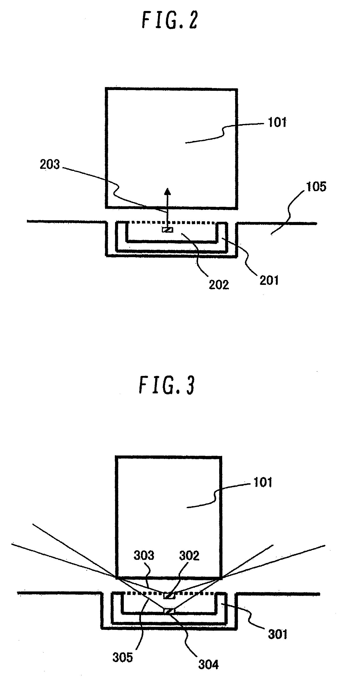
[0024]FIG. 3 illustrates a third embodiment of the present invention. It shows how direct light from the luminescent-substance-included fluid in the vessel is received by the detector when measurement is being performed. The range 1303 of direct light incident on the detector 101 from a luminescent substance 1 (302) in a vessel 301 is wider than the range 2 (305) of direct light incident on the detector 101 from a luminescent substance 2 (304) which is farther from the detector 101 than the luminescent substance 1 (302). In terms of the amounts of direct light, this means that the detector receives more light from the luminescent substance 1 (302) that is located closer to the detector than from the luminescent substance 2 (304) that is located farther from the detector.

[0025]Thus, it is possible to detect more direct light by forming the vessel so that the luminescent-substance-included fluid contained therein is located nearer to a measuring tool and scattered more thinly or subst...


PUM


Abstract

To increase the direct light received by the detector and decrease reflections from the detection component support structures, the luminescent substance is placed as close to the detector as possible. More specifically, the apparatus is configured so as to slide out a structure shielding the detector from light and at the same time slide in the vessel containing the luminescent substance therein until the vessel comes right under the detector. The invention can detect trace luminescence from a small-volume sample by maximizing the amount of direct light received from the sample and minimizing the decay of indirect light received from the sample attributable to interactions with the vessel for containing the sample therein, the structure for collecting light, and the structure for supporting other detection components.

Description

BACKGROUND OF THE INVENTION[0001]1. Field of the Invention[0002]The present invention relates to an apparatus which quantifies faint fluorescent or phosphorescent luminescence which is biologically, chemically or electrochemically generated. In particular, the invention relates to a luminescence measuring apparatus which uses a photomultiplier tube for measurement.[0003]2. Description of the Related Art[0004]As a qualitative / quantitative analysis technique, it is known to use a substance which specifically binds to a constituent of the object to be assayed. The substance is labeled, and the constituent is identified and quantified by measuring the label. This technique is particularly effective when the amount of the constituent of interest is very small and therefore has been used in determining the presence or absence of antigens, antibodies, enzymes and particular genetic sequences in biological samples. In the past, a radioactive substance or the like was used as the label. Howe...

Claims


Application Information

Patent Timeline
IPC IPC(8): G01J1/00
CPCG01N21/645
Inventor TANOUE, HIDETSUGUISHIZAWA, MASATOSUZUKI, YOICHIRO
Owner HITACHI HIGH-TECH CORP
Why Eureka
Try Eureka