Method and system for reducing transceiver power via a variable symbol rate

Active Publication Date: 2008-09-18
AVAGO TECH INT SALES PTE LTD
View PDF35 Cites 26 Cited by
  • Summary
  • Abstract
  • Description
  • Claims
  • Application Information

AI Technical Summary

Benefits of technology

[0008]A system and/or method is provided for reducing transceiver power via a variable symbol rate, substantially as

Problems solved by technology

Moreover, cost considerations are driving a demand to increase the capabilities of existing copper cabling infrastructures.
A

Method used


Image

  • Method and system for reducing transceiver power via a variable symbol rate
  • Method and system for reducing transceiver power via a variable symbol rate
  • Method and system for reducing transceiver power via a variable symbol rate

Examples


Embodiment Construction

[0017]Certain embodiments of the invention may be found in a method and system for reducing transceiver power via a variable symbol rate. In this regard, an Ethernet transmitter may be enabled to transmit data at a variable symbol rate, wherein the symbol rate is determined based on a state of a link coupled to said Ethernet transmitter and / or resources available to said Ethernet transmitter. In this regard, link state may comprise one or more of, for example, available bandwidth, bit error rate, packet error rate, and link utilization; and resources may comprise one or more of, for example, power, buffer space, and processor time. Accordingly one or more threshold for link state and / or resources may be determined and the symbol rate may be adjusted when those thresholds are exceeded. Aspects of the invention may enable defining and / or transmitting unique symbols to identify possible symbol rates and / or a change in symbol rate.

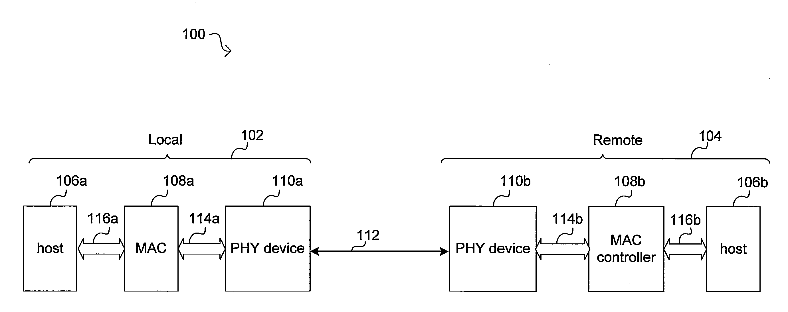
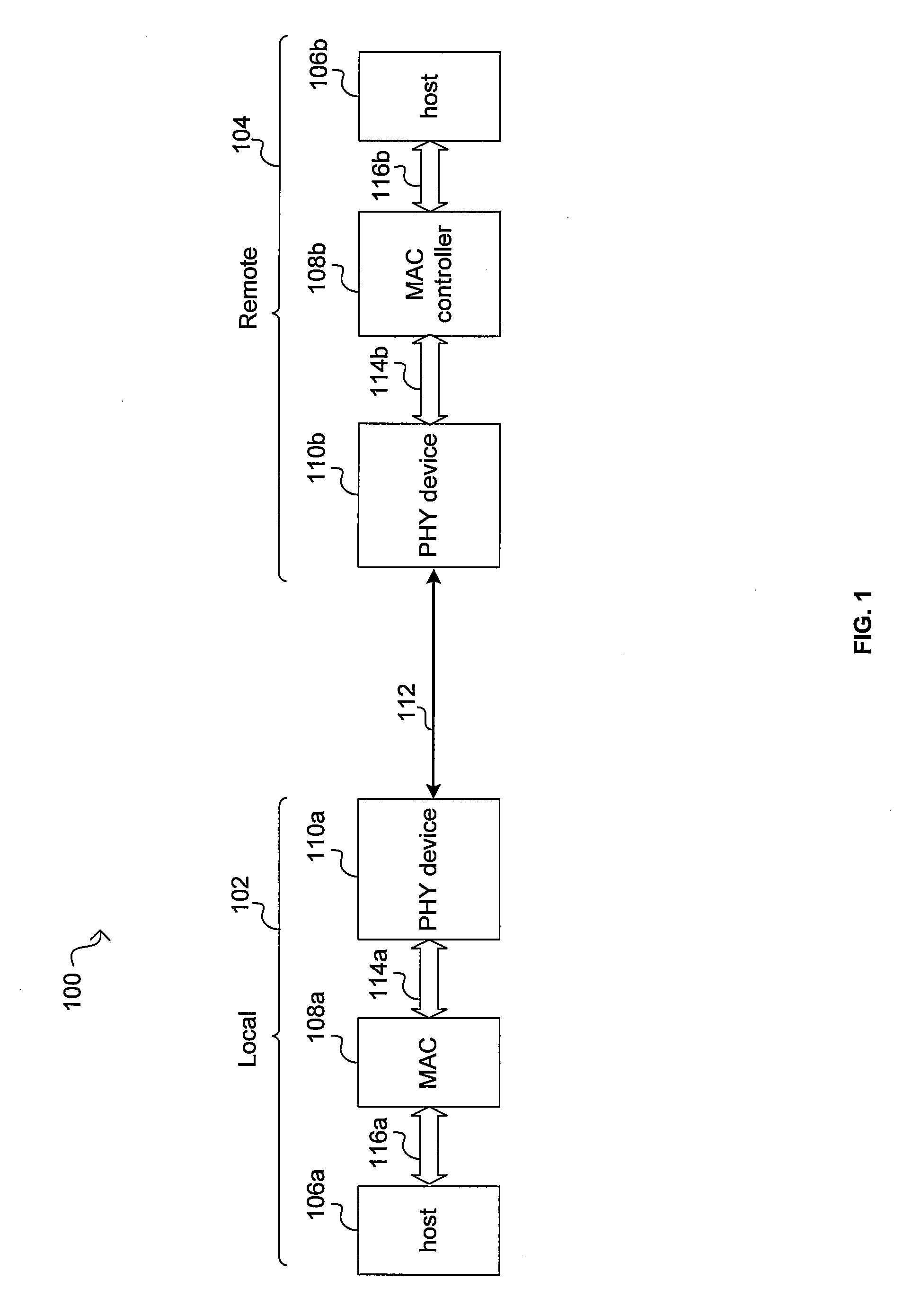
[0018]FIG. 1 is a block diagram illustrating an Ethernet...


PUM


Abstract

Aspects of a method and system for reducing transceiver power via a variable symbol rate are provided. In this regard, an Ethernet transmitter may be enabled to transmit data at a variable symbol rate, wherein the symbol rate is determined based on a state of a link coupled to said Ethernet transmitter and/or resources available to said Ethernet transmitter. In this regard, link state may comprise one or more of, for example, available bandwidth, bit error rate, packet error rate, and link utilization; and resources may comprise one or more of, for example, power, buffer space, and processor time. Accordingly one or more threshold for link state and/or resources may be determined and the symbol rate may be adjusted when those thresholds are exceeded. Aspects of the invention may enable defining and/or transmitting unique symbols to identify possible symbol rates and/or a change in symbol rate.

Description

CROSS-REFERENCE TO RELATED APPLICATIONS / INCORPORATION BY REFERENCE[0001]This patent application makes reference to, claims priority to and claims benefit from U.S. Provisional Patent Application Ser. No. 60894240 filed on Mar. 12, 2007.[0002]This patent application also makes reference to, claims priority to and claims benefit from U.S. Provisional Patent Application Ser. No. 60917870 filed on May 14, 2007.[0003]This application also makes reference to:U.S. patent application Ser. No. ______ (Attorney Docket No. 18600US02) filed on even date herewith;U.S. patent application Ser. No. ______ (Attorney Docket No. 18603US02) filed on even date herewith; andU.S. patent application Ser. No. ______ (Attorney Docket No. 18365US02) filed on even date herewith.[0004]Each of the above stated applications is hereby incorporated herein by reference in its entirety.FIELD OF THE INVENTION[0005]Certain embodiments of the invention relate to networking. More specifically, certain embodiments of the ...

Claims


Application Information

Patent Timeline
IPC IPC(8): H04L12/413
CPCH04L12/413H04L12/40039Y02B60/31Y02B60/35H04L12/40136Y02D30/50
Inventor POWELL, SCOTT
Owner AVAGO TECH INT SALES PTE LTD
Why Eureka
Try Eureka