
Image scanning apparatus and image scanner

a scanning apparatus and scanner technology, applied in the direction of electrographic process, instruments, transportation and packaging, etc., can solve the problems of deterioration of scanning image quality, and the apparatus disclosed in japanese patent publication laid-open no. 2006-16093 is not suitabl

Active Publication Date: 2008-09-18
MURATA MASCH LTD
View PDF8 Cites 10 Cited by
  • Summary
  • Abstract
  • Description
  • Claims
  • Application Information

AI Technical Summary

Benefits of technology

[0008]In order to overcome the problems described above, preferred embodiments of the present invention provide a document tray elevation control which is provided for both the case in which the scanning is performed based on the image quality and the case in which the scanning is performed quickly.
[0011]Accordingly, the document tray can be elevated by selecting the control mode from the two control modes, i.e., the first control mode in which the transfer (image scanning) of the document is suspended and the transfer (scanning) is resumed after the document tray is elevated, and the second control mode in which the document tray is elevated while the transfer (image scanning) of the document is continued. As a result, the document tray can properly be elevated according to the appropriate circumstances.
[0013]Accordingly, in the image-quality-priority scanning mode, the document tray can be elevated in the first control mode such that the elevation of the document tray does not adversely affect the image quality in scanning the document. On the other hand, in the speed-priority scanning mode, the document tray is elevated in the second control mode, so that the document can be efficiently scanned to complete the scanning work in a short time.
[0015]Therefore, in the second control mode, because the number of documents transferred during the elevation of the document tray depends on the document scanning speed, the additional elevating distance can be determined according to the number of documents. Accordingly, the upper surface height of the documents is substantially elevated to the target height irrespective of the document scanning speed, which allows the transfer unit to smoothly transfer the documents.

Problems solved by technology

Accordingly, in Japanese Patent Publication Laid-Open No. 2006-16093, when the document tray is elevated during scanning of the document, the document is moved by an elevation of the document tray during transportation of the document, resulting in the deterioration of the scanning image quality.
In particular, the apparatus disclosed in Japanese Patent Publication Laid-Open No. 2006-16093 is not suitable in the case where the scanning is performed to emphasize image quality.

Method used


Image

  • Image scanning apparatus and image scanner
  • Image scanning apparatus and image scanner
  • Image scanning apparatus and image scanner

Examples


Embodiment Construction

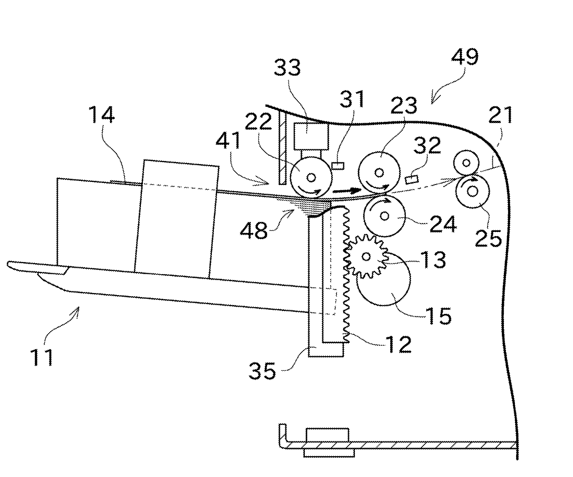
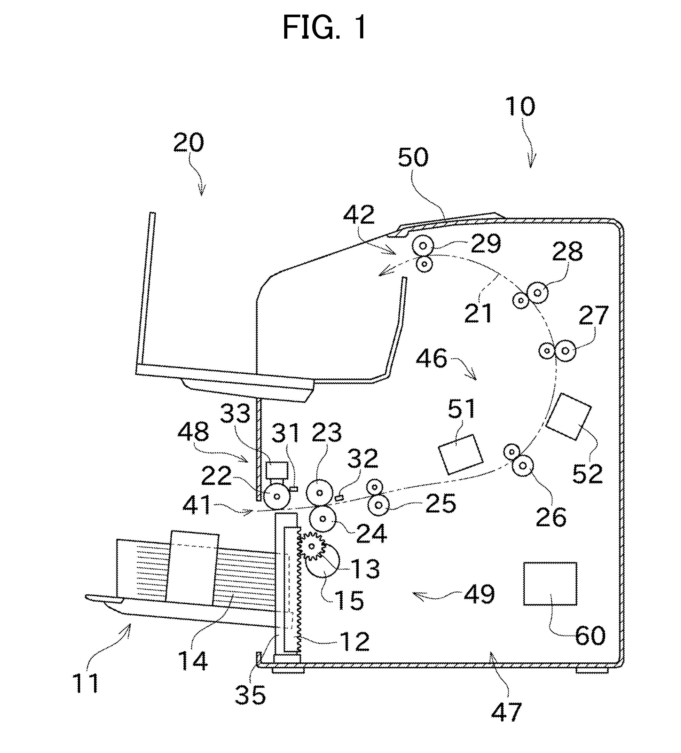
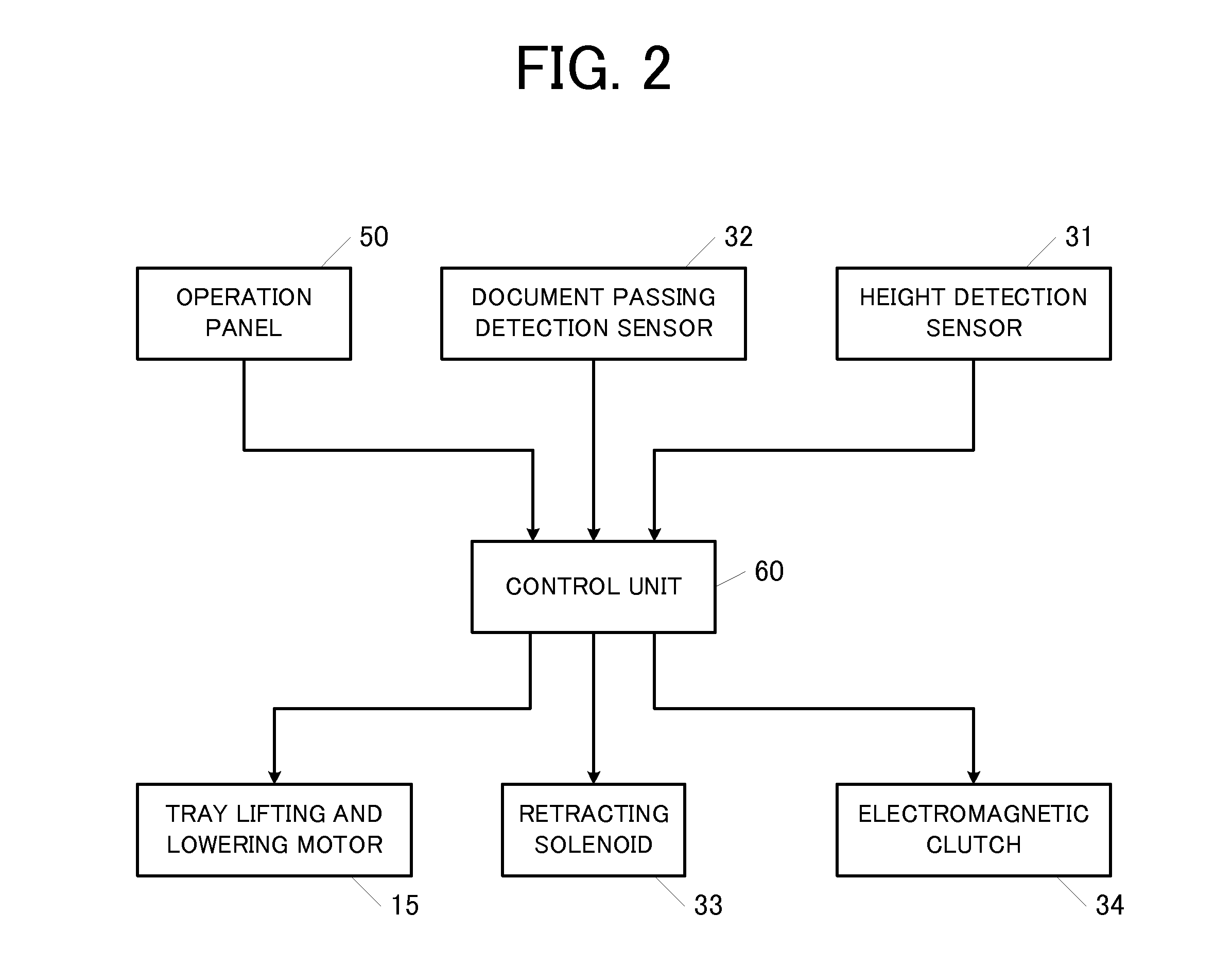
[0025]Preferred embodiments of the present invention will be described below. FIG. 1 is a sectional side view illustrating an entire configuration of an image scanner according to a preferred embodiment of the present invention, and FIG. 2 is a block diagram illustrating a portion of an electronic configuration of the image scanner. FIG. 3 is an enlarged sectional side view illustrating a state in which a transfer unit is driven to transfer a topmost document into a document transportation path. FIG. 4 is an enlarged sectional side view illustrating a state in which a pickup roller is retracted upward immediately before the transfer of the topmost document is completed. FIG. 5 is an enlarged sectional side view illustrating a state in which the transfer is completed to lower the pickup roller again. FIG. 6 is an enlarged sectional side view illustrating a state in which a document tray is elevated. FIG. 7 is a flowchart illustrating document tray elevation control.

[0026]As illustrat...


PUM


Abstract

In an image scanning apparatus, documents on a document tray are transferred one by one, and an upper surface height of the documents is lowered to turn off a height detection sensor. Different kinds of control modes are performed according to a document scanning mode. In an image-quality-priority scanning mode, a transfer unit suspends transfer of the document, the document tray is elevated until the upper surface height reaches a target height that is higher by a predetermined distance after the height detection sensor is turned on, and the transfer unit resumes the transfer of the document. In a speed-priority scanning mode, while the transfer of the document is continued by the transfer unit, the document tray is elevated until the document tray reaches the target height.

Description

CROSS-REFERENCE TO RELATED APPLICATIONS[0001]This application claims priority under 35 U.S.C. 119 to Japanese Patent Application No. 2007-67358, filed on Mar. 15, 2007, which application is hereby incorporated by reference in its entirety.BACKGROUND OF THE INVENTION[0002]1. Field of the Invention[0003]The present invention relates to a configuration of an image scanning apparatus suitably used to place and scan a large amount of documents.[0004]2. Description of the Related Art[0005]For example, Japanese patent Laid-Open application publication No. 2006-16093 discloses a copying machine which includes an upper-limit position detection sensor for detecting a topmost document while being able to accommodate plural documents on a document tray (document feeder tray). In the copying machine disclosed in Japanese patent Laid-Open application publication No. 2006-16093, when the number of documents is decreased as the documents on the document tray are fed, a control device controls a tra...

Claims


Application Information

Patent Timeline
Patent Type & Authority Applications(United States)
IPC IPC(8): G03G15/00
CPCB65H1/18B65H3/06H04N2201/33328H04N1/2032H04N1/193H04N1/121H04N1/0443H04N1/0408H04N1/00652H04N1/00649H04N1/00631H04N1/0062H04N1/00567B65H2513/514B65H2513/512B65H7/18B65H2405/15B65H2511/20B65H2511/22B65H2511/414B65H2220/01B65H2220/03B65H2220/02B65H2220/11
Inventor OSHIMA, OSAMU
Owner MURATA MASCH LTD
Learn More