Installation of Underwater Anchorages

a technology for installing anchorages and underwater, which is applied in the direction of sea energy generation, bulkheads/piles, tidal stream/damless hydropower, etc. it can solve the problems of high cost, cost-effective cost, and the need for expensive offshore vessels to achieve cost-effectively. achieve the effect of cost-effectiv

Active Publication Date: 2008-09-18
SABELLA
View PDF6 Cites 27 Cited by
  • Summary
  • Abstract
  • Description
  • Claims
  • Application Information

AI Technical Summary

Benefits of technology

[0009]A method in accordance with the present invention provides a cost-effective means of carrying out drilling in cases where beds are hard or rocky. Such a method can be employed to install a wide range of piles, from shallow-embedment “shear keys” to deeper pile embedments capable of carrying uplift forces. The technique is generic and therefore suitable for any type of seabed anchorage or mooring; however, the main applications discussed below are foundations for ocean and water current energy systems, for example wave, tidal stream and offshore wind energy conversion systems.

Problems solved by technology

This becomes expensive in water depths of more than approximately 30 m because it can no longer be carried out using relatively cheap and available near-shore construction jack-up vessels, but instead requires expensive specialist offshore vessels such as mobile drilling units (MDUs) or dynamically positioned (DP) drilling ships.
This is a significant extension of current operating envelopes, and there are currently no indications that this could be achieved cost-effectively.
The problems associated with using a conventional large diameter rotary drill are firstly that there is little if any of such equipment capable of operation underwater, and secondly that the equipment is large and relatively complex, and requires to be mounted on a structure which can react the large torques generated.
The drill string is heavy and the vessel required to deploy it is correspondingly large.
In the offshore environment, however, it has only previously been deployed using surface-breaking rigid drill stringers operated from stable drilling stringers.

Method used


Image

  • Installation of Underwater Anchorages
  • Installation of Underwater Anchorages
  • Installation of Underwater Anchorages

Examples


Embodiment Construction

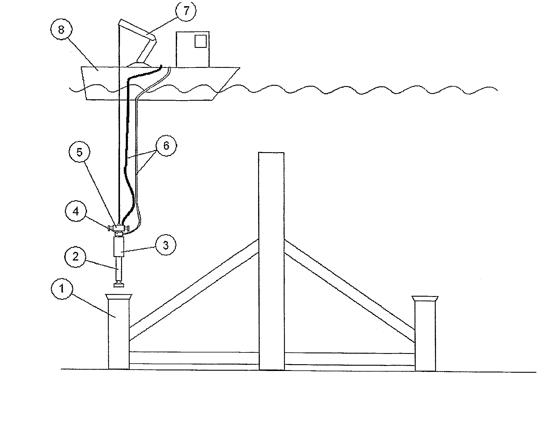
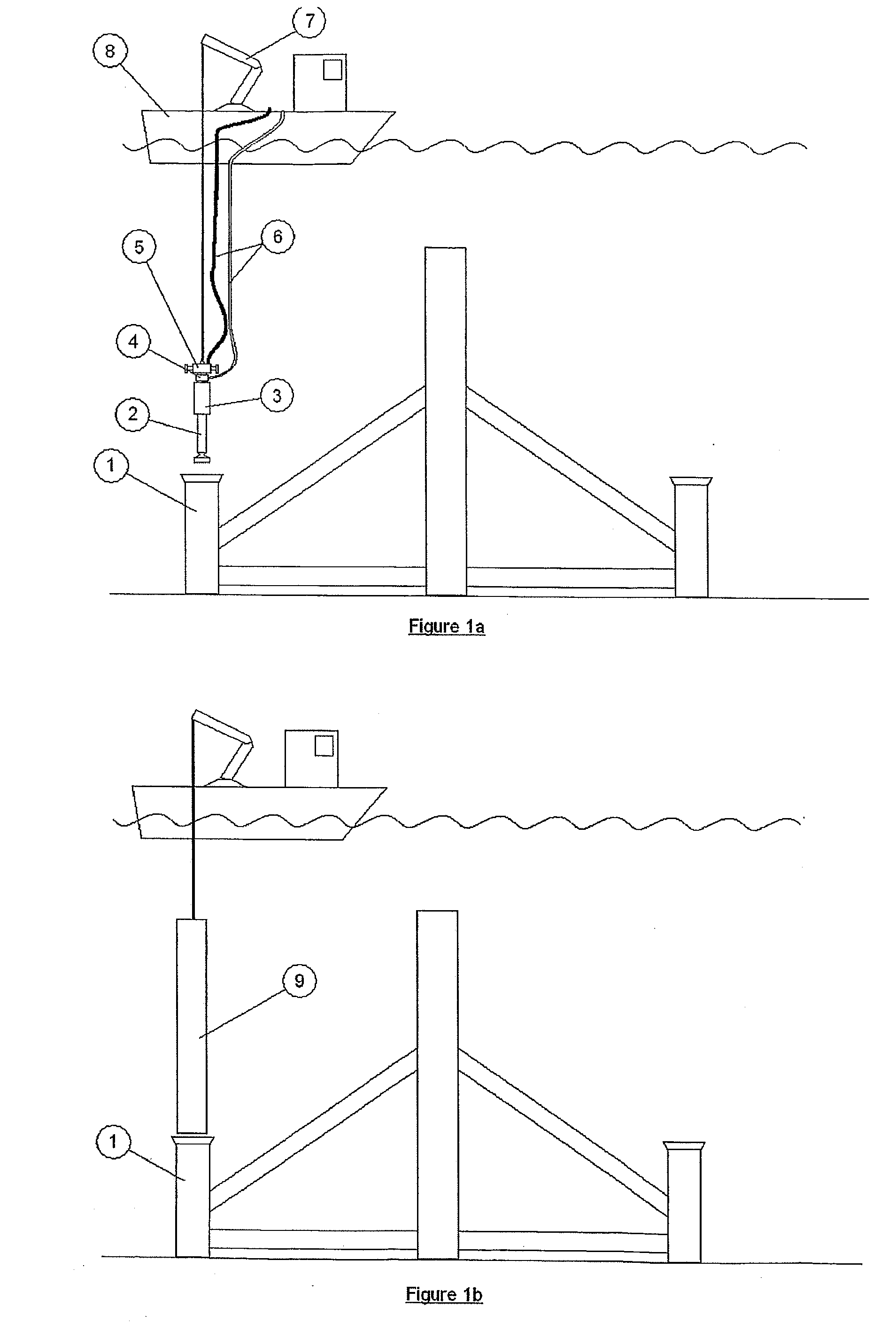
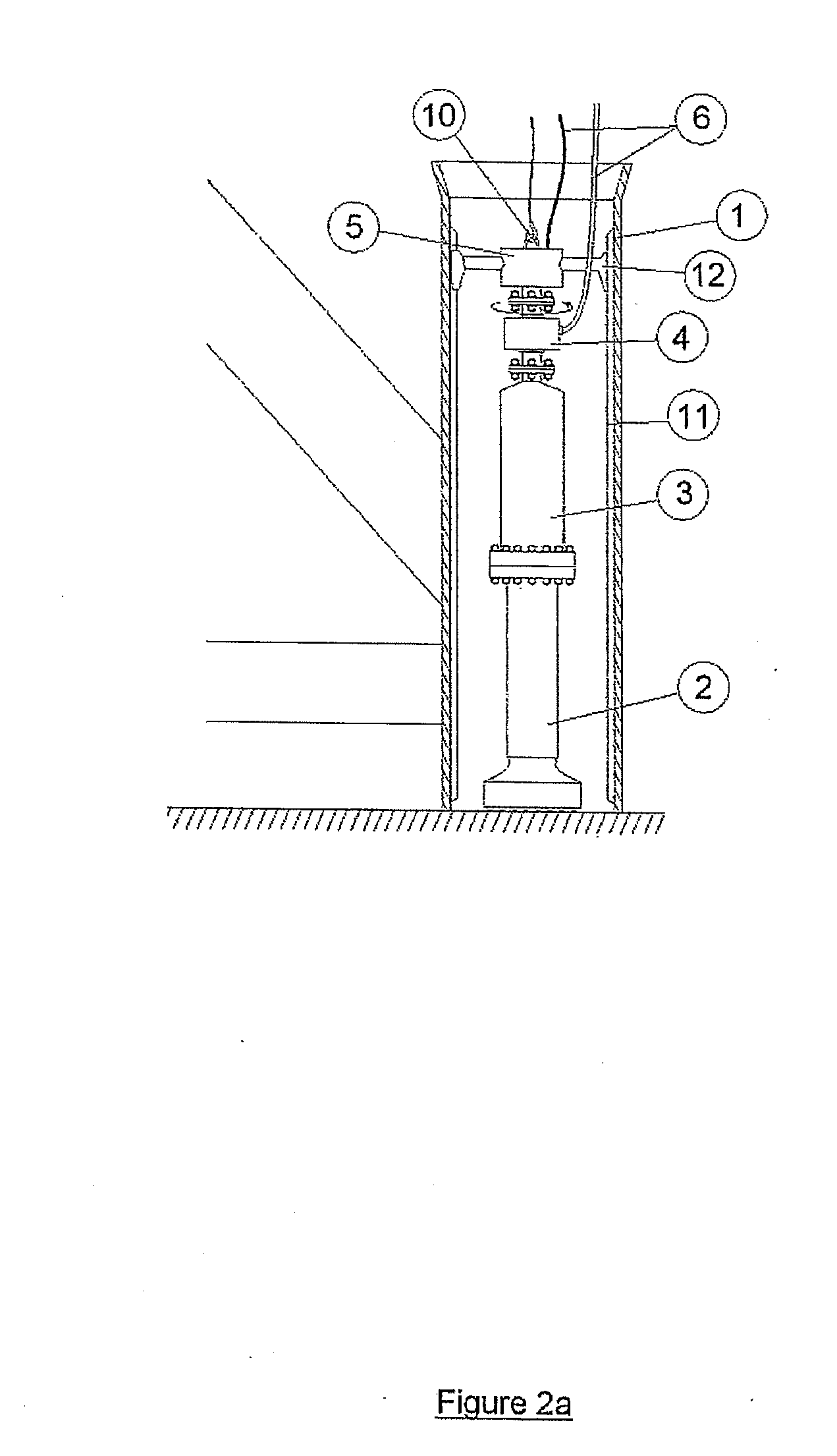
[0014]Referring to FIG. 1a, a support structure is positioned on the bed of a body of water. The support structure comprises a central column 30 stabilized by support feet in the form of hollow members 1. In an alternative embodiment there may be only one hollow member, which may be positioned substantially centrally within the support structure.

[0015]A workboat 8 lowers a drill string down into one of the hollow members 1. The drill string is an axial assembly comprising all the equipment necessary to operate the drill, such that all equipment may be recovered by the workboat 8 in a single lift after drilling. This may include, but is not restricted to, weights, drive motors for slow indexing of the drill bit, power swivel to receive the power for the drill from an umbilical whilst allowing the drill to index around, and guidance channels to control the exhaust fluid velocity to ensure the removal of drillings.

[0016]In the embodiment shown in FIG. 1a, the drill string is a percussi...


PUM


Abstract

A method of securing a load bearing structure to the bed of a sea, river or estuary. The method comprises placing the load bearing structure on the bed; forming a pile-receiving hole in the bed by means of drilling equipment which is connected to a surface vessel by flexible lines only so that the weight of the drilling equipment is supported by the bed, the drilling equipment being guided by the load bearing structure, and the load bearing structure resisting any non-vertical loads imparted to the drilling equipment; and withdrawing the drilling equipment and installing an attachment pile within the formed hole.

Description

[0001]This invention relates to a method of securing a load bearing structure to the bed of a sea, river or estuary, and is particularly, although not exclusively, concerned with the installation of anchorages for structures such as power generating equipment using water current energy. The present invention also relates to a load bearing structure in combination with drilling equipment for use in securing the load bearing structure.BACKGROUND[0002]It is becoming clear that many sites for water current energy systems comprise hard or rocky beds. Existing methods of drilling underwater rock sockets typically require a fixed drilling platform such as a jack-up vessel. This becomes expensive in water depths of more than approximately 30 m because it can no longer be carried out using relatively cheap and available near-shore construction jack-up vessels, but instead requires expensive specialist offshore vessels such as mobile drilling units (MDUs) or dynamically positioned (DP) drilli...

Claims


Application Information

Patent Timeline
Patent Type & Authority Applications(United States)
IPC IPC(8): E02D5/40E02D13/04E02D27/52
CPCE02D5/40E02D13/04Y02E10/28F03B13/264E02D27/52Y02E10/30E02D7/00Y02E10/20
Inventor GIBBERD, GEORGEHUXLEY-REYNARD, CHRISTOPHER
Owner SABELLA
Why Eureka
Try Eureka