Rotating Stirring Device with Substantially Narrow Distribution of Energy Dissipation Rate

a technology of rotating stirring and energy dissipation rate, which is applied in the direction of clay mixing apparatus, thin-film liquid gas reaction, transportation and packaging, etc., can solve the problems of small reactor volume, poor mixing in the gap, and damage to the bio-cells contained in the system

Inactive Publication Date: 2008-09-18
ETH ZZURICH
View PDF3 Cites 29 Cited by
  • Summary
  • Abstract
  • Description
  • Claims
  • Application Information

AI Technical Summary

Problems solved by technology

A common shortcoming of the ST reactors is a broad distribution of the energy dissipation rate (defined as energy dissipated per unit mass) in the mass contained in the reactors, which is undesired for processes that are sensitive to the local energy dissipation rate.
For a bio-reaction process, when the distribution of the energy dissipation rate is broad, the large energy dissipation rates in the tail of the distribution lead to large turbulent shear rate, which can damage the bio-cells contained in the system.
When the rotating speed is low, the Couette flow reactor can generate very uniform laminar shear rate, but mixing in the gap is generally very poor.
Moreover, to get sufficiently large shear rate for practical applications, the gap between the cylinders must be very small, leading to very small volume of the reactor, which becomes meaningless in industrial applications.
However, the TC reactors have the following common disadvantages (see Haut et al, 2003 (Ref 3); Drozdov, 2002 (Ref 4); Resende et al, 2001 (Ref 5)): (1) poor mass transfer within the vortices, (2) possible separation of components in the gap when there is a difference in the density between components, and (3) a large drag torque and high power input per unit volume.
However, manufacturing and scaling-up of such designed reactors are challenging.
It is obvious that this type of reactor is not suitable for those reactions, where an intimate intensive mixture between the various reaction components has to be achieved.
Thus, this type of reactor has the same drawback as the ST reactors.

Method used


Image

  • Rotating Stirring Device with Substantially Narrow Distribution of Energy Dissipation Rate
  • Rotating Stirring Device with Substantially Narrow Distribution of Energy Dissipation Rate
  • Rotating Stirring Device with Substantially Narrow Distribution of Energy Dissipation Rate

Examples


example 1

Distribution of the Energy Dissipation Rate in a Stirred Tank (ST) Reactor

[0041]FIG. 8 shows a section view of the ST reactor of the prior art 3, composed of a cylindrical body 4, a six-blades Rushton turbine 5 and four baffles 6 symmetrically placed inside the reactor. The real sizes of the various elements of the reactor employed in the CFD simulations are as follows:

A=B=270 mm; C=90 mm; D=93 mm; E=18.6 mm; F=23.25 mm; G=27 mm.

[0042]Using Fluent, the volume-based distribution of the energy dissipation rate for the ST reactor geometrically defined above, has been computed with a rotation speed for the Rushton turbine being 8.08 rev / s. The results are reported in FIG. 10 with symbols (*). The abscissa is the normalized energy dissipation rate, defined as the energy dissipation rate divided by the volume-averaged energy dissipation rate. The volume-averaged energy dissipation rate at this rotation speed is computed to be 1.15 m2 / s3. It is seen that the distribution is very broad, cov...

example 2

Distribution of the Energy Dissipation Rate in a Taylor Couette (TC) Reactor

[0043]FIG. 9 shows a section view of the TC reactor of the prior art 7, composed of an outer cylinder 8, an inner cylinder 9. Both cylinders have cross-section of circular shape, and they are placed concentrically. The inner cylinder is rotating. The real sizes of the various elements of the reactor employed in the CFD simulations are as follows:

1=140 mm; J=8 mm; K=320 mm.

[0044]The distribution of the energy dissipation rate computed using Fluent for the TC reactor geometrically defined above is shown in FIG. 10 with symbols (o TC8). The rotation speed of the inner cylinder employed for the computations is 8.31 rev / s, and this leads to the computed volume-averaged energy dissipation rate to be 1.15 m2 / s3, equal to that in Example 1. The results indicate that the distribution of the energy dissipation rate of the TC reactor is narrower than that of the ST reactor, particularly without the tail in the range of...

example 3

Distributions of the Energy Dissipation Rate in the Reactors of a Triangle-Inner Cross-Section of the Inner Member (TIC) According to the Present Invention

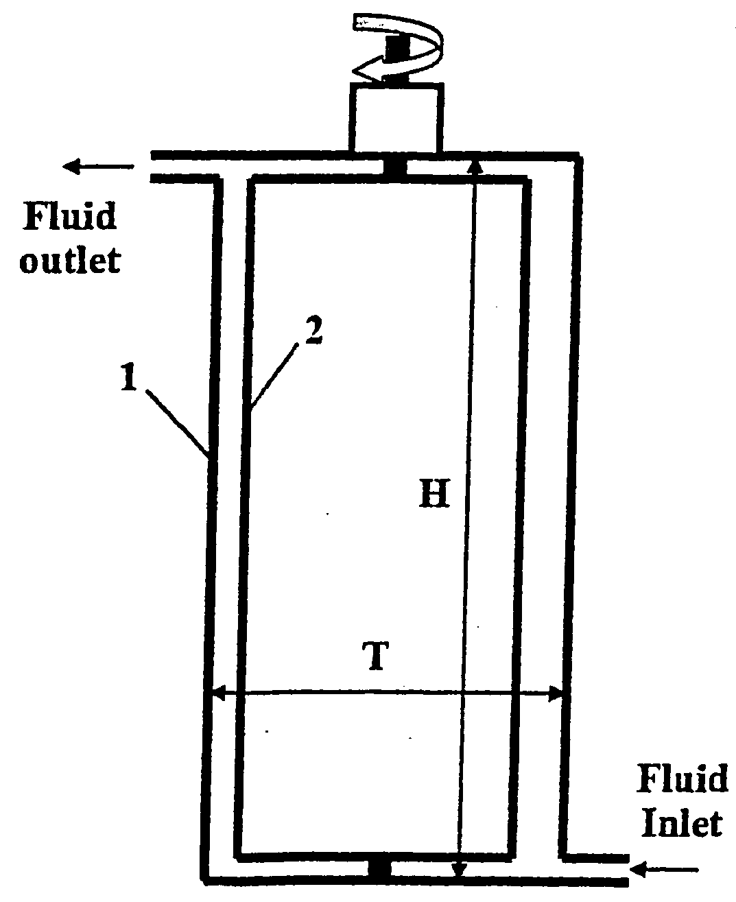
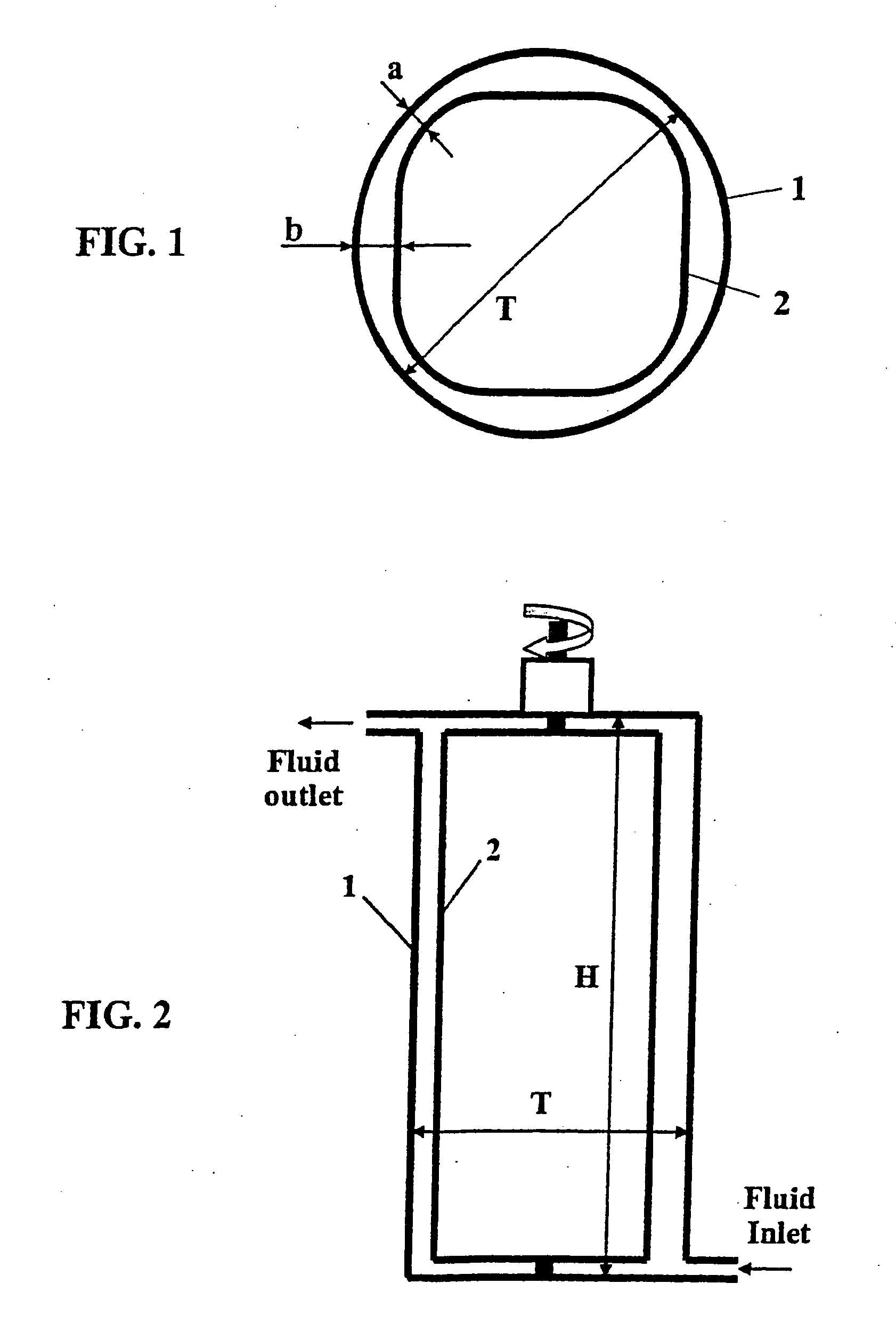
[0045]According to the present invention as schematically illustrated in FIG. 1 and FIG. 2, e.g. a triangle cross-section of the inner member perpendicular to the rotation axis is employed for the CFD simulations. The real sizes of the various elements of the reactor employed in the simulations are as follows: T=140 mm; H=320 mm; a=8 mm, but three values have been employed for b=12 mm, 16 mm, and 22 mm, thus leading to three different designs of the present invention.

[0046]The distributions of the energy dissipation rate computed using fluent for the three reactors geometrically defined above are shown in FIG. 10 with symbols, * TIC8-12 for b=12 mm, □ TIC8-16 for b=16 mm, and ▴ TIC8-22 for b=22 mm. The rotation speeds of the inner member employed for the computations are 5.75 rev / s, 5.59 rev / s, and 5.72 rev / s, respectively for the...


PUM

PropertyMeasurementUnit
radiiaaaaaaaaaa
radiiaaaaaaaaaa
distanceaaaaaaaaaa

Abstract

A rotating stirring device for generating substantially narrow distribution of energy dissipation rate and avoiding presence of Taylor vortices is disclosed. The device includes an outer member (1) such as a cylinder with cross-section of circular shape and an inner member (2) with cross-section of equilateral or inequilateral polygon shape with curved cusps. The inner member is preferably concentrically placed within the outer cylinder and rotates. Such device is particularly advantageous as a reactor or mixer for processes where chemical and physical properties are sensitive to the variations in the shear rate and for processes that involve fragile components. The device can be also used to replace Taylor Couette device for the purposes of improving mass transfer and of avoiding separate of components in the gap in the case of presence of differences in density among components.

Description

RELATED APPLICATION[0001]This application is a U.S. National Phase application under 35 USC § 371 of International Application PCT / CH2004 / 000494, filed Aug. 6, 2004, and claims priority under 35 USC §119 of European application no. 03018073.1, filed Aug. 8, 2003, and European application no. 03019330.4, filed Aug. 27, 2003.FIELD OF THE INVENTION[0002]The present invention relates to a rotating stirring and / or reacting device particularly suitable for mixing processes that require substantially narrow distribution of energy dissipation rate.BACKGROUND OF THE INVENTION[0003]Various types of mechanically stirred reactors are known in the art, generally of cylindrical body, and equipped along their axis with a stirring system, which is commonly a stirrer (turbine, impeller, propeller, blade, etc.) or a group of stirrers. These reactors are hereinafter referred to as “ST (stirred tank) reactors”. The ST reactors are used for processes that require continuous mixing of various components ...

Claims


Application Information

Patent Timeline
Patent Type & Authority Applications(United States)
IPC IPC(8): B01F7/28B01J19/18B01F27/94B01J10/02
CPCB01F7/008B01F7/0085B01F7/28B01F15/00909B01F15/065B01J2219/00094B01F2215/0431B01F2215/0463B01F2215/0481B01J10/02B01J19/1887B01F15/068B01F27/272B01F27/40B01F27/94B01F35/54B01F35/92B01F35/95
Inventor MORBIDELLI, MASSIMOSOOS, MIROSLAVWU, HUA
Owner ETH ZZURICH
Why Eureka
Try Eureka