Electrocautery method and apparatus

a technology of electrodes and electrodes, applied in the field of tissue cauterization, can solve the problems of small size of electrode structures, difficult to remove intact most organs, and time-consuming and laborious sealing of blood vessels

Inactive Publication Date: 2008-09-18
AESCULAP AG
View PDF109 Cites 58 Cited by
  • Summary
  • Abstract
  • Description
  • Claims
  • Application Information

AI Technical Summary

Benefits of technology

[0011]An electrode structure and a mechanism for automated or user-selected operation or compensation of the electrodes, for example to determine tissue coverage and / or prevent arcing between bottom electrodes during electrocautery is disclosed.

Problems solved by technology

In minimally invasive surgical procedures, sealing of blood vessels can be especially time consuming and problematic because there is limited access via a cannula and other small passages.
Most organs are too large to be removed intact through a cannula or other limited access passage, thus requiring that the tissue be morcellated, e.g. cut, ground, or otherwise broken into smaller pieces, prior to removal.
In this respect, one problem recognized by the inventors concerns the small size of today's electrode structures.
This small electrodes strategy results in the surgeon having to seal and divide multiple times to seal and divide long tissue sheets adequately.
Such time consuming processes are also detrimental to patients, increasing anesthetic time and potentially increasing the risk of injury to surrounding structures, as the delivery of energy and division of tissue is repeated again and again.
This condition can cause electrical arcing, tissue charring, and inadequate tissue sealing.
Mechanical, e.g. blade, or electrosurgical division of tissue is performed immediately following tissue sealing, and the division of inadequately sealed tissue can pose a risk to the patient because unsealed vessels may hemorrhage.
Arcing presents its own set of problems.
Furthermore, depending upon the path of the arc, this might damage non-targeted tissue.
Another problem is that adjacent electrodes in a multiple electrode system may generate electrical cross-talk or generate excessive thermal effect in the transition zone between two adjacent electrodes that fire sequentially.
However, this standoff prevented very thin tissue from making contact with the opposing electrodes, preventing an optimal electrical seal in these regions.
These standoffs, if too shallow, can also result in arcing between electrodes.
Thus, to ascertain the adequacy of tissue electrode coverage based solely on local impedance is imprecise and impractical.

Method used


Image

  • Electrocautery method and apparatus
  • Electrocautery method and apparatus
  • Electrocautery method and apparatus

Examples


Embodiment Construction

[0018]In view of the problems of conventional technology that the inventors have recognized (as discussed above), the inventors have sought to improve the ability of a user to control electrocautery electrodes after said electrode have been inserted into the body. Further areas of their focus include improving the efficiency of transferring power to electrode structures, and improving the accuracy of measurements taken from the electrode structure in situ. One benefit of implementing these improvements is the ability to use larger electrode surfaces, with the advantageous consequences discussed above.

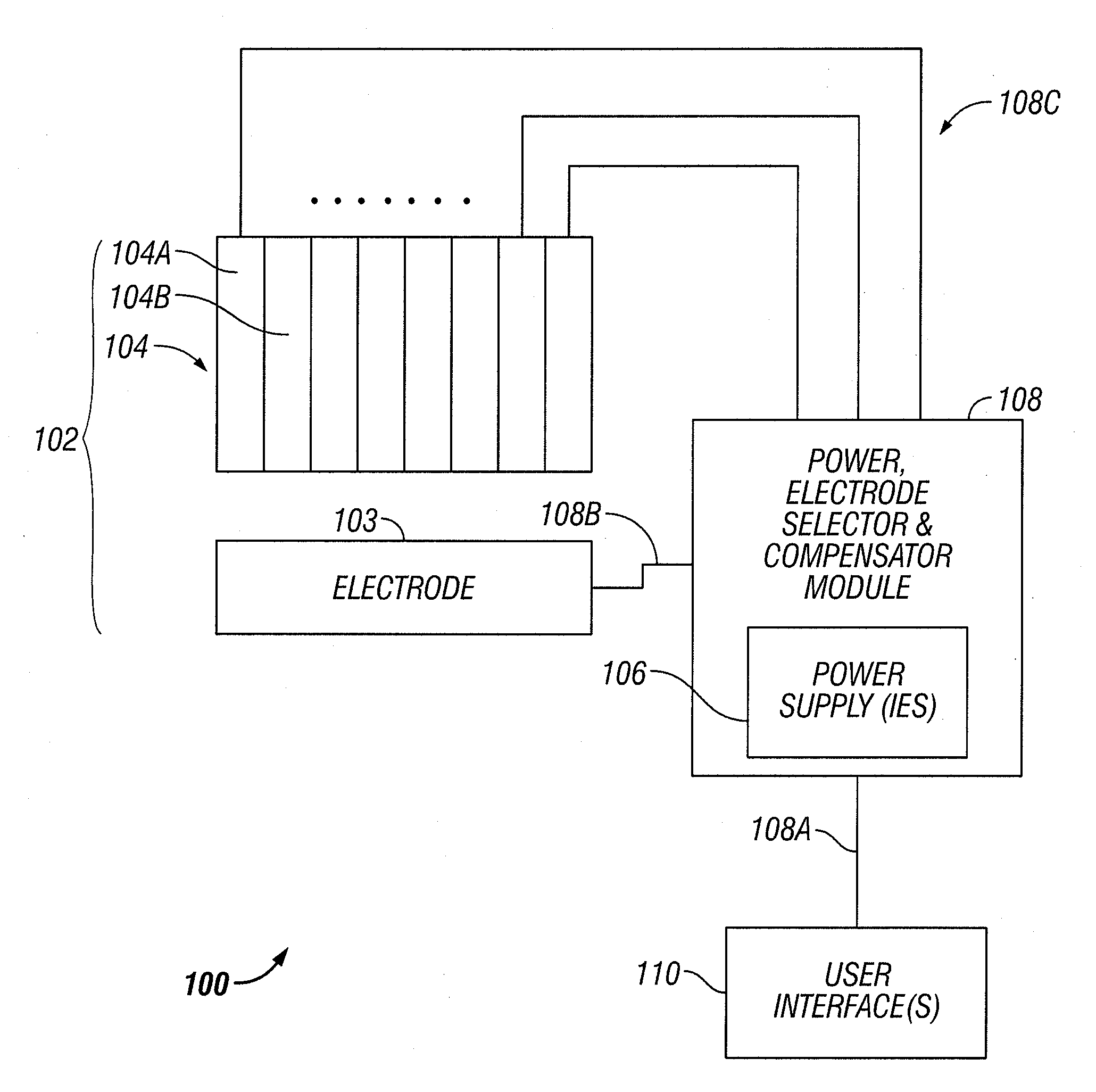
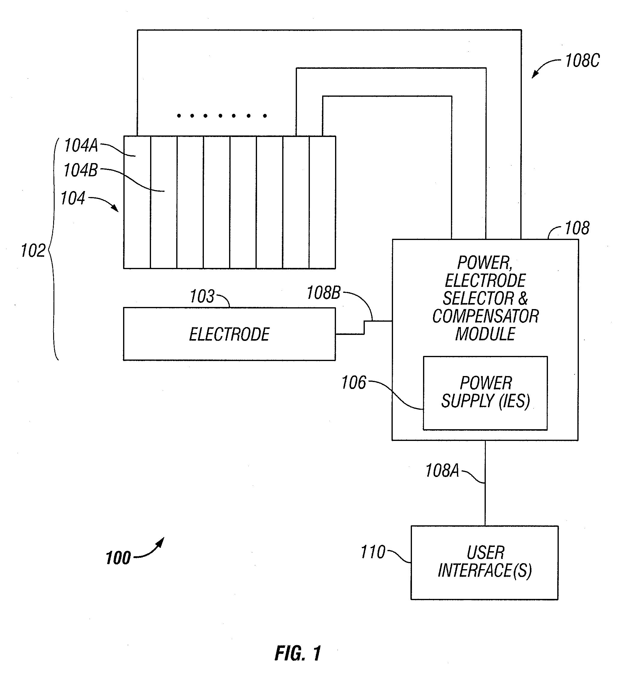
[0019]FIG. 1 illustrates one embodiment of electrocautery system 100. The system 100 includes an electrode structure 102 that is electrically driven by a power, electrode selector, and compensator module 108. The module 108 is operated in accordance with user input conveyed via one or more user interfaces 110.

[0020]As explained below in greater detail, certain components of the system 1...


PUM


Abstract

An electrode structure and a mechanism for automated or user-selected operation or compensation of the electrodes, for example to determine tissue coverage and / or prevent arcing between bottom electrodes during electrocautery is disclosed.

Description

CROSS-REFERENCE TO RELATED APPLICATIONS[0001]This application is a divisional of U.S. patent application Ser. No. 11 / 671,891, filed Feb. 6, 2007 (Attorney Docket No.: ARAG0016), which is a continuation-in-part of U.S. application Ser. Nos. 11 / 382,635 filed May 10, 2006 (Attorney Docket No.: ARAG002) and 11 / 371,988 filed Mar. 8, 2006 (Attorney Docket No.: ARAG0003), and claims the benefit thereof in accordance with 35 USC 120. U.S. application Ser. No. 11 / 382,635 filed May 10, 2006 in turn, claims the benefit of provisional applications 60 / 725,720 filed on Oct. 11, 2005 (Attorney Docket No. ARAG0001 PR) and 60 / 680,937 filed on May 12, 2005 (Attorney Docket No. ARAG005PR). The entireties of the foregoing applications are incorporated herein by this reference thereto.BACKGROUND OF THE INVENTION[0002]1. Field of the Invention[0003]The invention relates to tissue cauterization. More particularly, the invention concerns an electrocautery system with various electrodes and a mechanism for ...

Claims


Application Information

Patent Timeline
Patent Type & Authority Applications(United States)
IPC IPC(8): A61B18/18
CPCA61B18/1442A61B2018/00505A61B2018/00595A61B2018/0063A61B2018/00875A61B2018/00702A61B2018/00791A61B2018/00827A61B2018/00678A61B2018/165A61B2018/147A61B2018/124A61B18/14A61B18/12
Inventor EDER, JOSEPH CHARLESNORDELL, BENJAMIN THEODOREEDELSTEIN, PETER SETHNEZHAT, CAMRANKANE, MARK
Owner AESCULAP AG
Why Eureka
Try Eureka