

Curved Panel for Acoustical Shell, Method of Manufacturing the Same, and Acoustical Shell Using the Same
- Summary
- Abstract
- Description
- Claims
- Application Information
AI Technical Summary
Benefits of technology
Problems solved by technology
Method used
Image

Examples
Embodiment Construction
[0032]Hereinafter, the preferred embodiments of the present invention will be described in detail with reference to the accompanying drawings. It should be noted that the drawings of the embodiments described below are attached to help in understanding the present invention but not to limit the scope of the present invention.
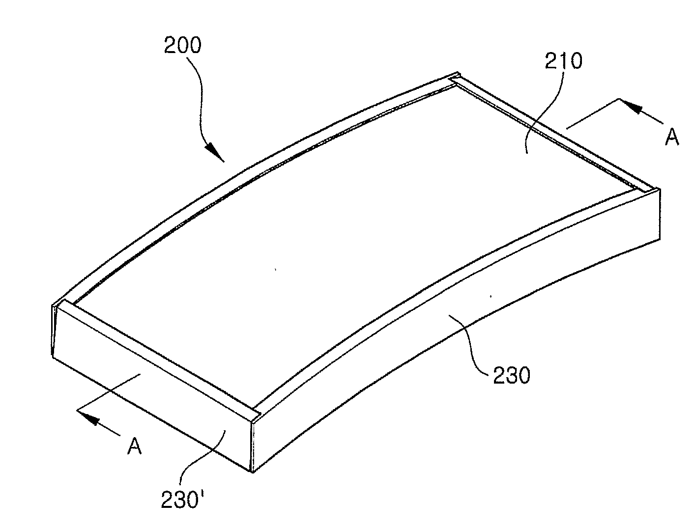
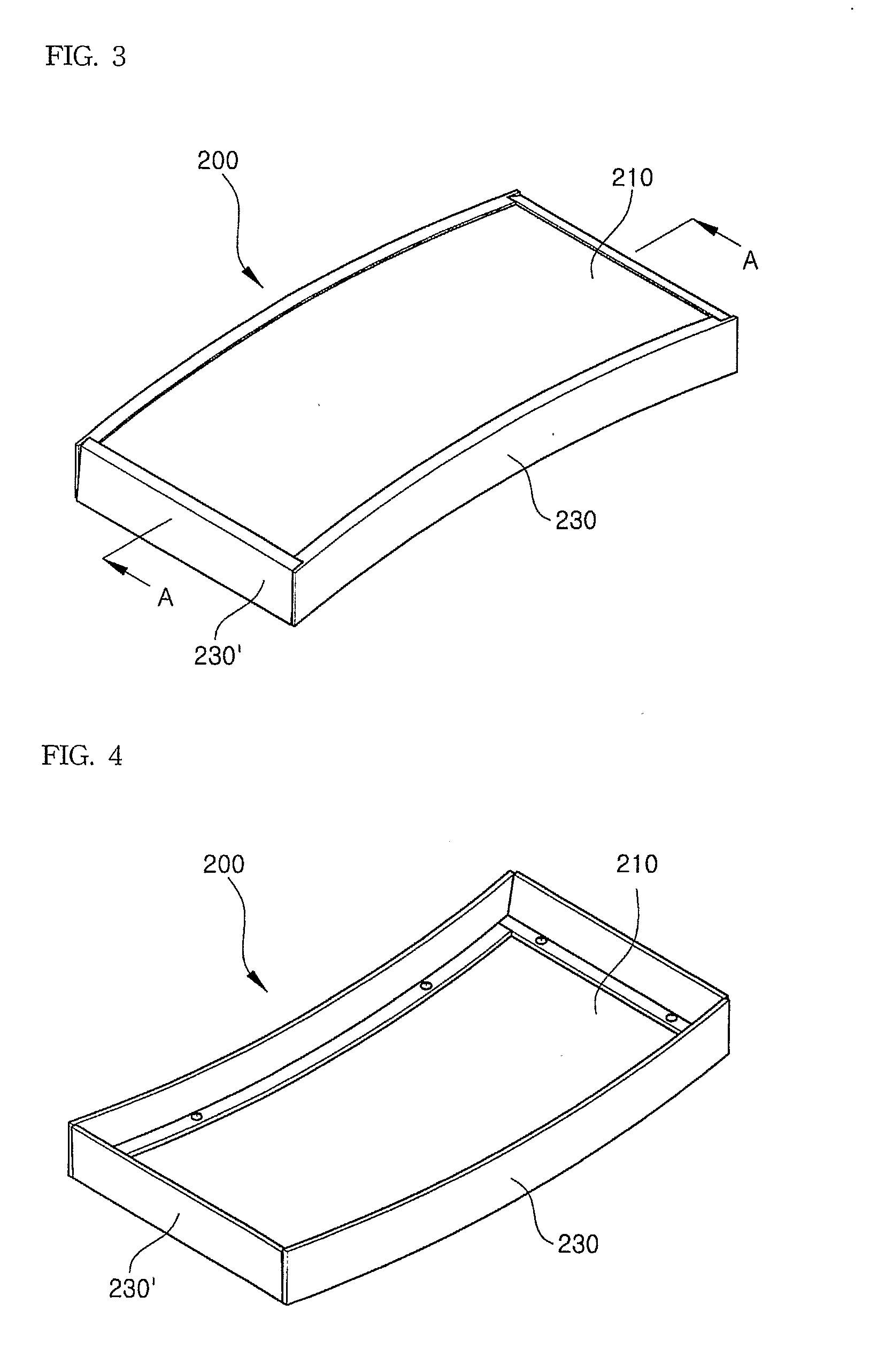
[0033]FIG. 3 through FIG. 5 are perspective views of an acoustical shell according to one embodiment of the present invention. FIG. 3 is a plane perspective view of the acoustical shell of the embodiment, FIG. 4 is a rear perspective view of the same, and FIG. 5 is an exploded perspective view. FIG. 6 shows a partial cross sectional view, taken along the line A-A of FIG. 3, and FIG. 7 shows a partial longitudinal sectional view of the acoustical shell of FIG. 3.
[0034]With reference to FIG. 3 through FIG. 7, a curved panel 210 for an acoustical shell in accordance with the present invention comprises an upper board 211 having a structure in that a melamine pasteb...
PUM
| Property | Measurement | Unit |
|---|---|---|
| Angle | aaaaa | aaaaa |
| Thickness | aaaaa | aaaaa |
Abstract
Description
Claims
Application Information