Oscillation circuit and the method for using the same

Inactive Publication Date: 2008-09-25
ADVANCED ANALOG TECH INC
View PDF2 Cites 0 Cited by
  • Summary
  • Abstract
  • Description
  • Claims
  • Application Information

AI Technical Summary

Benefits of technology

[0008]The oscillation circuit of the present invention uses less chip area but achieves the purpose of limiting the effect of temperature variation upon frequency to the range of ±2%. Besides, the oscillation circuit of the present invention selectively excludes the resistor REXT and capacitor CEXT therein, and thus suffers less from the process variation.

Problems solved by technology

Besides, prior art oscillation circuits usually embed the resistor R1 and capacitor C1 inside the analog chip, which causes the operating frequency to become more susceptible to temperature and process variation.
As far as the backlight control ICs that exist in the market are concerned, users usually request the effect of temperature variation upon frequency to be limited to a range of ±2%, and therefore prior art circuits do not fulfill the requirements of the current design trend any more.
However, the circuit designs of FIGS. 3(a) and 3(b) waste too much chip area and thus do not satisfy efficient design methodology.

Method used


Image

  • Oscillation circuit and the method for using the same
  • Oscillation circuit and the method for using the same
  • Oscillation circuit and the method for using the same

Examples


Embodiment Construction

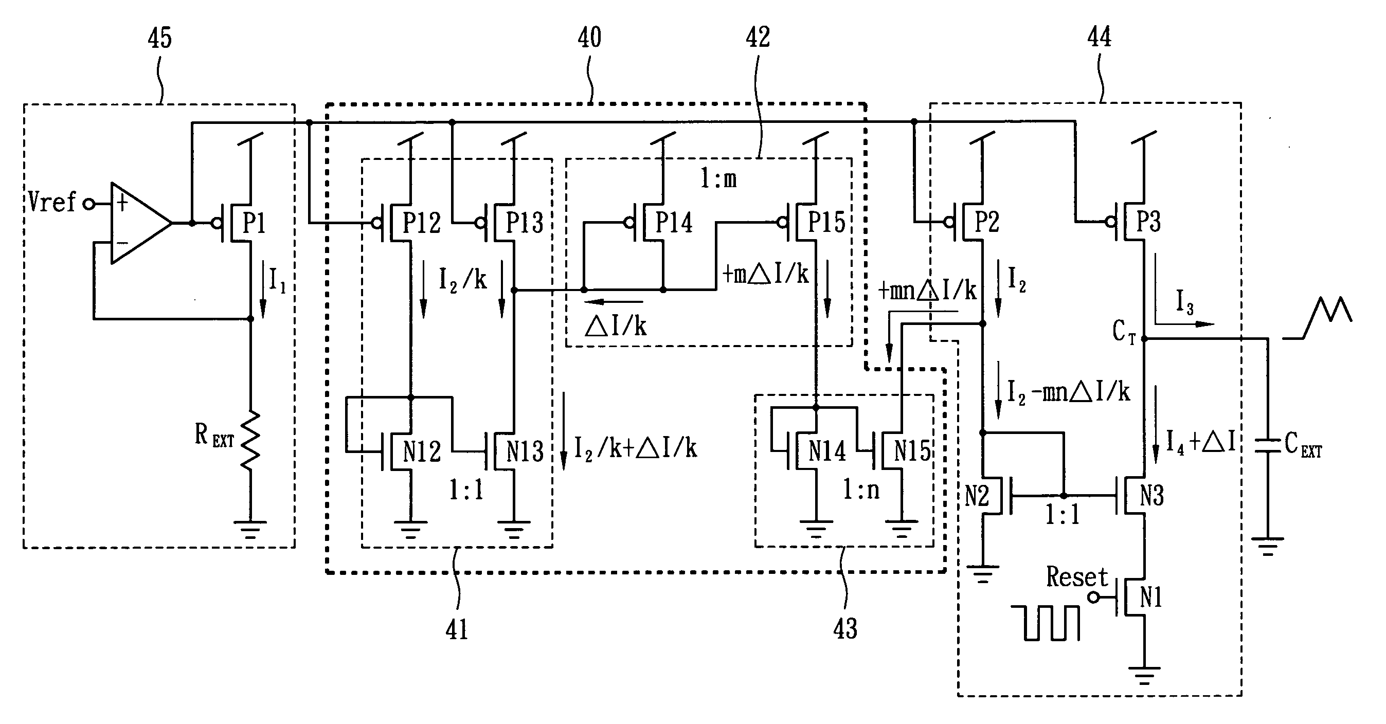
[0017]FIG. 4 shows an oscillation circuit according to an embodiment of the present invention. The oscillation circuit includes a compensation current mirror 40 and an output current mirror 44, while the compensation current mirror 40 is located between the oscillation current generating stage 45 and the output current mirror 44. The compensation current mirror 40, which is for use in offsetting current variation of the output current mirror 44 caused by temperature variation, includes a P-N complementary current mirror 41, a P-type current mirror 42 and an N-type current mirror 43. The P-N complementary current mirror 41 has the same structure as the output current mirror 44, but is only 1 / k times the scale of the output current mirror 44. Therefore, the current of the P-N complementary current mirror 41 is only 1 / k times that of the output current mirror 44, where k is greater than 1. The P-type current mirror 42 connects to the P-N complementary current mirror 41, and because the...


PUM


Abstract

The oscillation circuit includes an output current mirror, a P-N complementary current mirror, a P-type current mirror and an N-type current mirror. The P-N complementary current mirror has the same structure as the output current mirror but has current that is only 1 / k times the current of the output current mirror, wherein k is greater than 1. The P-type current mirror connects to the P-N complementary current mirror, and has current that is m times the current of the P-N complementary current mirror, where m is greater than 1. The N-type current mirror has one end connected to the P-type current mirror and another end connected to the output current mirror. The N-type current mirror has current that is n times the current of the P-type current mirror, wherem×nk≥1,and n is greater than 1.

Description

BACKGROUND OF THE INVENTION[0001]1. Field of the Invention[0002]The present invention relates to a high precision oscillation circuit, and more particularly, to a high precision oscillation circuit which can control the effect of temperature variation upon frequency within a specific range.[0003]2. Description of the Related Art[0004]FIG. 1 shows a corresponding diagram of frequency variation versus voltage gain for a piezoelectric device. The piezoelectric device is usually used in a backlight module of an LCD monitor, and therefore its operating frequency will affect the brightness of the LCD monitor. As far as the analog circuit controls the piezoelectric device, the magnitude of the output circuit will affect the operating frequency of the piezoelectric device. Therefore, finding a method to control the output current of the analog circuit in order to insulate it from temperature variation is an important topic.[0005]FIG. 2 is a prior art oscillation circuit, which includes an o...

Claims


Application Information

Patent Timeline
IPC IPC(8): H03L1/00
CPCG05F3/262H03L1/022H03K5/2481H03K5/08
Inventor CHIEN, MAO CHUANSUN, YU MINCHU, CHU YU
Owner ADVANCED ANALOG TECH INC
Why Eureka
Try Eureka