Eureka AIR delivers breakthrough ideas for toughest innovation challenges, trusted by R&D personnel around the world.

Image forming apparatus

a technology of image forming apparatus and forming apparatus, which is applied in the direction of electrographic process apparatus, printing, instruments, etc., can solve the problems of color misalignment and inability to align, and achieve the effect of improving the accuracy of color alignment in the image forming apparatus

Active Publication Date: 2008-09-25
RICOH KK
View PDF17 Cites 6 Cited by
  • Summary
  • Abstract
  • Description
  • Claims
  • Application Information

AI Technical Summary

Benefits of technology

The present invention provides an image forming apparatus that can improve the accuracy of color alignment by controlling a correction pattern for the correction of color misalignment. This apparatus generates a color image on a transfer belt by superimposing toner images of respective colors generated by image forming units, and transfers the color image onto a transfer medium. The apparatus includes a correction pattern forming unit, a detection sensor, and a correction control unit. The correction control unit controls the width, length, or both of the correction pattern in response to an output of the detection sensor. This can lead to improved accuracy of color alignment and reduced color misalignment.

Problems solved by technology

In color image forming apparatuses having the above-noted configuration, toner images in respective colors may not be aligned at the correct position due to error in spacing between the axes of respective photoconductive drums, error in parallelism between the respective photoconductive drums, error in the position of a deflecting mirror for deflecting a laser beam in a light emission unit, error in the write timing of an electrostatic image on the photoconductive drums, and so on.
This gives rise to the problem of color misalignment.

Method used


Image

  • Image forming apparatus
  • Image forming apparatus
  • Image forming apparatus

Examples


first embodiment

[0023]A description will first be given of a

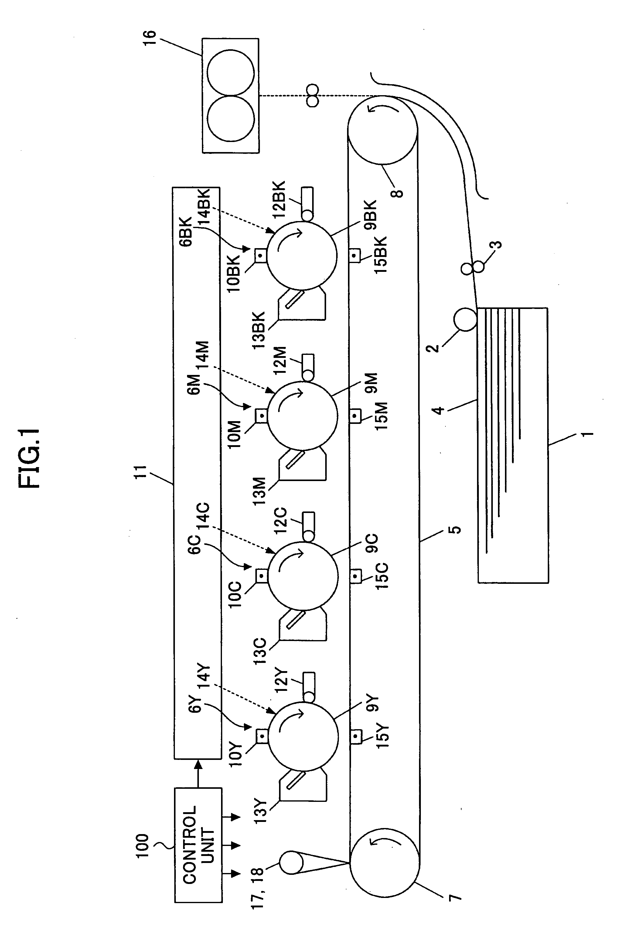
[0024]FIG. 1 is a block diagram showing the configuration of a color image forming apparatus according to an embodiment of the present invention. As shown in FIG. 1, the color image forming apparatus has image forming units for respective colors arranged in line along a transfer belt 5. This configuration is referred to as a tandem-type configuration.

[0025]Along the transfer belt 5, image forming units 6BK, 6M, 6C, and 6Y are arranged in the order listed, starting from the upstream side with respect to the travel direction of the transfer belt 5. The image forming units 6BK, 6M, 6C, and 6Y have an identical structure. The only difference is the colors of toner images formed by these units.

[0026]The image forming unit 6BK forms a black image. The image forming unit 6M forms a magenta image. The image forming unit 6C forms a cyan image. The image forming unit 6Y forms a yellow image. In the following, the image forming unit 6BK will specific...

second embodiment

[0053]In the following, a second embodiment will be described.

[0054]In the second embodiment, the image forming apparatus of the first embodiment is used, and the method of controlling a correction pattern is the same as that of the first embodiment. In the second embodiment, however, the control of a correction pattern is performed at constant intervals. Such constant intervals may be defined by the total number of printed sheets, the number of sheets printed by one job, etc.

third embodiment

[0055]In the following, a third embodiment will be described.

[0056]In the third embodiment, the image forming apparatus of the first embodiment is used, and the method of controlling a correction pattern is the same as that of the first embodiment. In the third embodiment, however, the control of a correction pattern is performed in response to a change in ambient temperature. Specifically, the control of a correction pattern may be performed in response to a change in ambient temperature by X° C.


PUM


Abstract

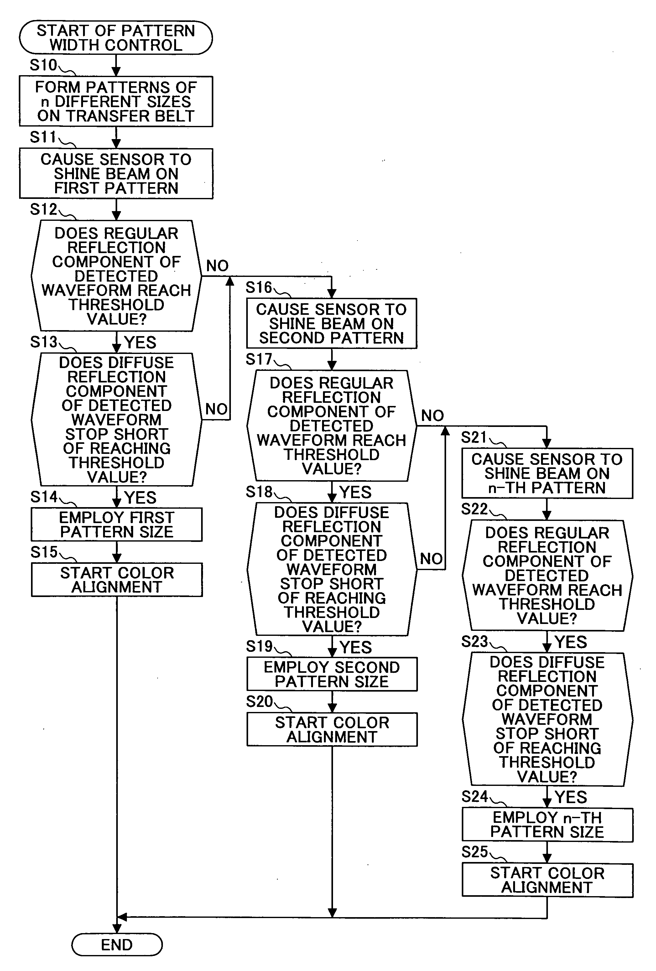
An image forming apparatus generates a color image on a transfer belt by superimposing toner images of respective colors generated by image forming units, and transfers the color image onto a transfer medium. The image forming apparatus includes a correction pattern forming unit configured to form a correction pattern for correcting color misalignment on the transfer belt, a detection sensor configured to detect the correction pattern formed on the transfer belt by the correction pattern forming unit, and a correction control unit configured to control a width of the correction pattern in response to an output of the detection sensor produced by detecting the correction pattern.

Description

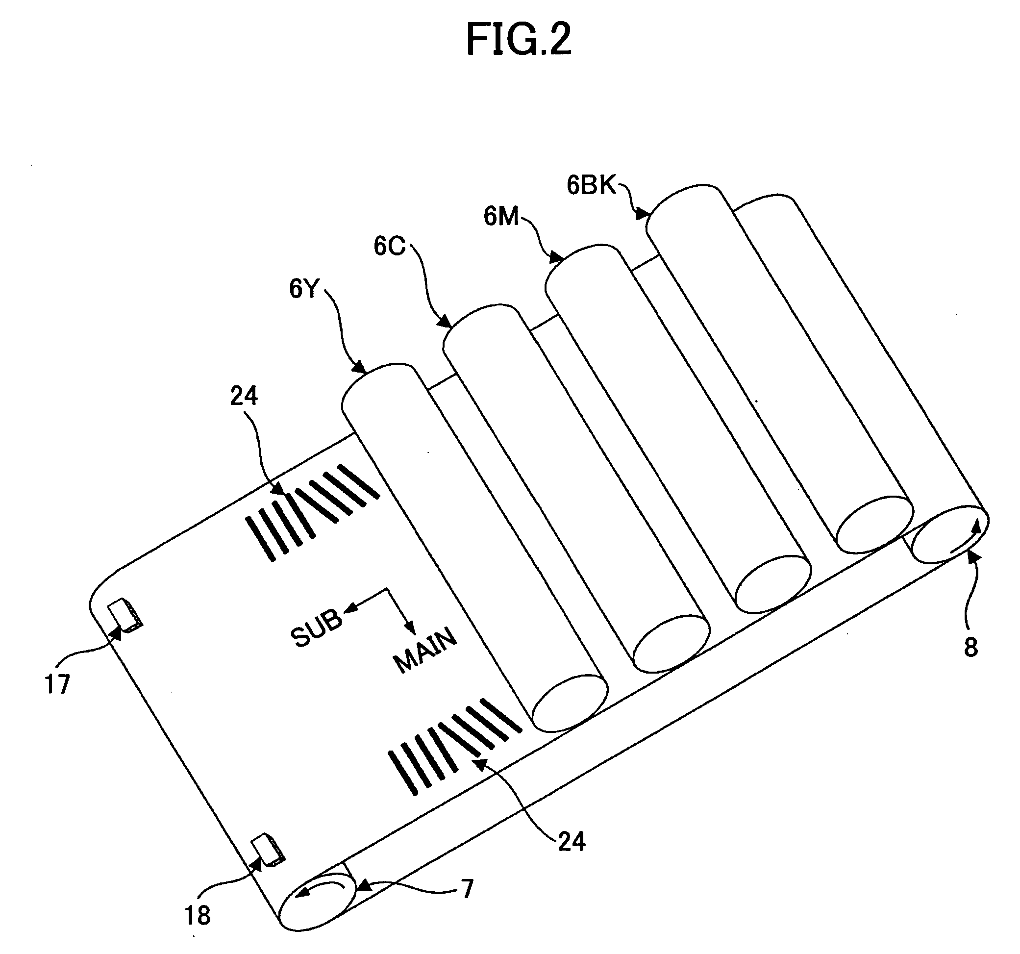
BACKGROUND OF THE INVENTION[0001]1. Field of the Invention[0002]The disclosures herein relate to the control of width of correction patterns used for the correction of color alignment in image forming apparatuses.[0003]2. Description of the Related Art[0004]In recent years, color image forming apparatuses have been widely used as apparatus for printing images. Color image forming apparatuses form a transfer color image on a transfer belt by superimposing toner images in respective colors created by electrostatic imaging processes. This transfer color image is then transferred onto a transfer sheet. In such color image forming apparatuses, a tandem-type configuration is widely used.[0005]In color image forming apparatuses having the above-noted configuration, toner images in respective colors may not be aligned at the correct position due to error in spacing between the axes of respective photoconductive drums, error in parallelism between the respective photoconductive drums, error ...

Claims


Application Information

Patent Timeline
Patent Type & Authority Applications(United States)
IPC IPC(8): G03G15/00
CPCG03G2215/0158G03G15/0131
Inventor KOMAI, KUNIHIRO
Owner RICOH KK
Why Eureka
Eureka Blog
Learn More