
Nut System and Aircraft Engine Mounting Structure Comprising Same

Active Publication Date: 2008-09-25
AIRBUS OPERATIONS (SAS)
View PDF15 Cites 11 Cited by
  • Summary
  • Abstract
  • Description
  • Claims
  • Application Information

AI Technical Summary

Benefits of technology

[0018]Thus, if the nut comes loose, the angular displacement of this nut is identical to the angular displacement of the threaded device to which it is coupled, but the difference in pitch between the main thread and the secondary thread means that these two elements will have a different linear displacement. Consequently, if this nut can loose in such a manner, it will quickly lock the nut system on its associated receiver assembly, which provides a quite satisfactory safety and reliability.
[0019]When this nut system according to the invention is used in combination with conventional anti-rotation means cooperating with the nut such as a serrated anti-rotation washer, the threaded device according to the system can be treated like an emergency device also called a <<Fail Safe>> device, to the extent that it can prevent the nut from current loose if the serrated washer should fail.

Problems solved by technology

However, it has been found that this type of arrangement cannot satisfy current safety requirements, that only offer a limited degree of safety.

Method used


Image

  • Nut System and Aircraft Engine Mounting Structure Comprising Same
  • Nut System and Aircraft Engine Mounting Structure Comprising Same
  • Nut System and Aircraft Engine Mounting Structure Comprising Same

Examples


Embodiment Construction

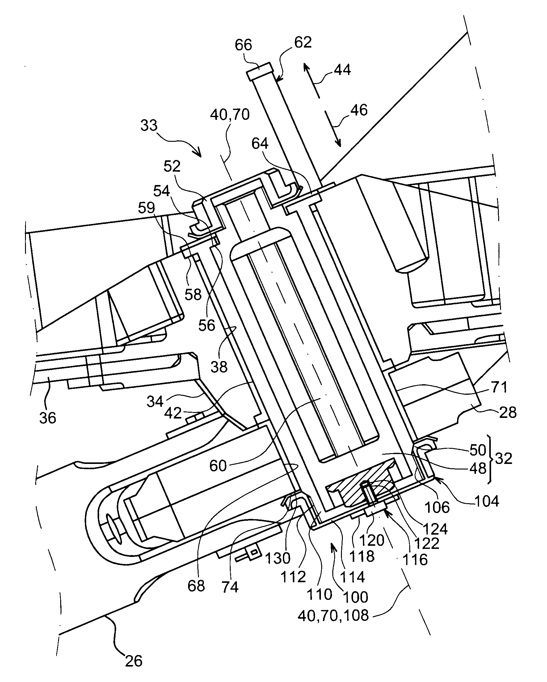
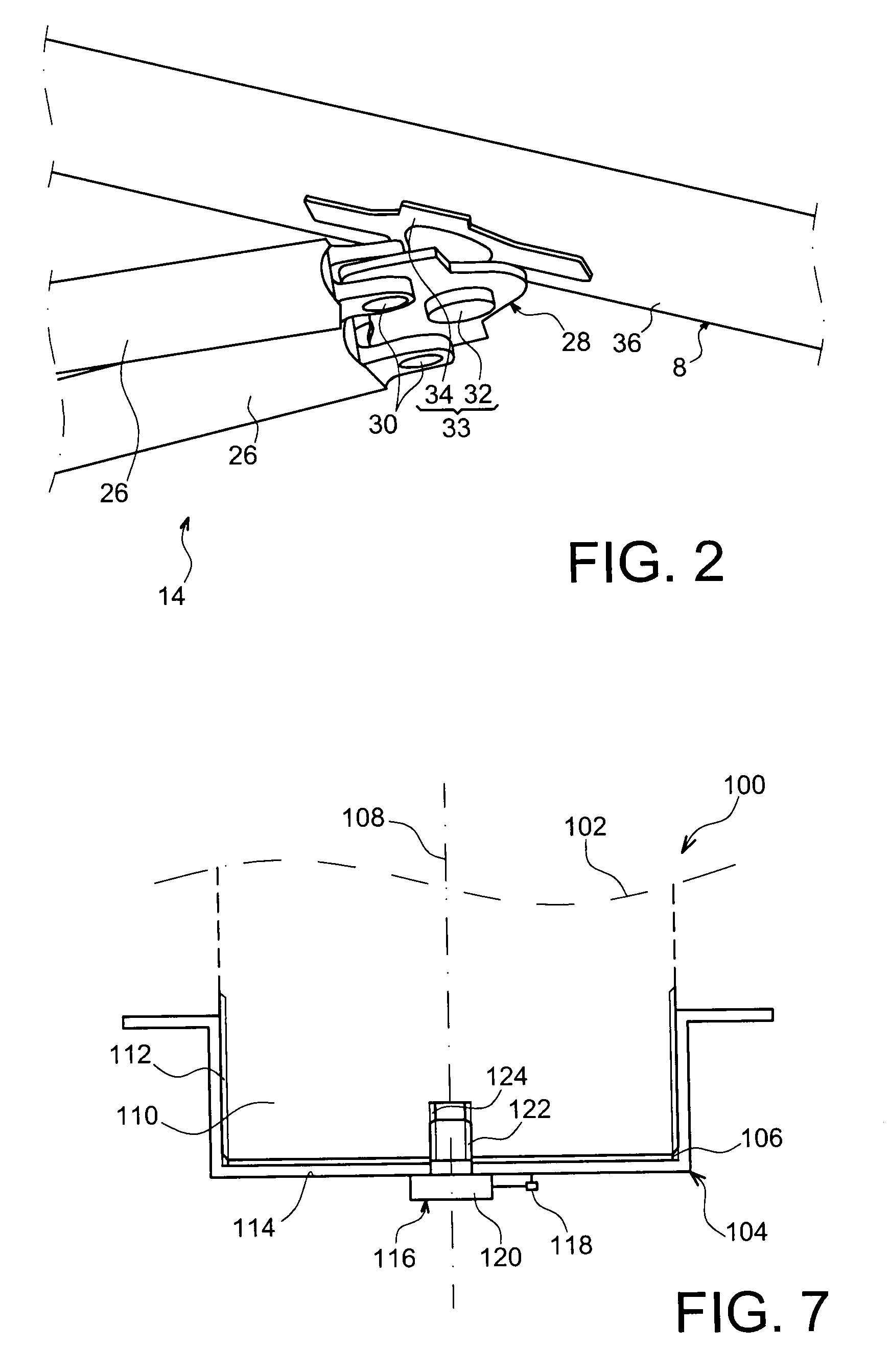
[0047]With reference firstly to FIG. 7, the figure shows a nut system 100 according to the principle of this invention, this system 100 being designed to be installed on an arbitrary receiving assembly 102.

[0048]The system 100 comprises a nut 104 provided with a principal inner thread 106, arranged along a screwing axis 108 also corresponding to a principal axis of the nut. The principal thread 106 has pitch p1 and is screwed onto a threaded end 110 of the receiving assembly 102 that has a complementary principal outer thread 112, also with pitch p1.

[0049]This nut 104 is provided with a cap 114 that closes it off, this cap being arranged orthogonal to the screwing axis 108.

[0050]There is also a threaded device 116 arranged along the screwing axis 108 such as a screw, arranged transverse to the cap 114 of the nut 104. This threaded device 116 is coupled in rotation with this nut 104 and is preferably fixed to it. This is achieved by the use of anti-rotation means 118 shown diagrammat...


PUM


Abstract

The invention relates to a nut system (100) comprising a nut (104) provided with a main thread (106) with pitch p1 and arranged along a screwing axis (108) of the nut. According to the invention, it also comprises a threaded device (116) coupled in rotation with the nut, this threaded device comprising a secondary non-screwed thread (122) on the main thread (106) from which it is separated, the secondary thread being arranged along the screwing axis and having a pitch p2 different from p1. Application of the invention with a device for resistance of thrusts generated by an aircraft engine.

Description

TECHNICAL DOMAIN[0001]This invention relates in general to the domain of nut systems used to create simple and secure mechanical links between different elements.[0002]It is particularly but not exclusively applicable to the field of aircraft engine suspension pylons, each pylon being designed to be inserted between an aircraft wing and its associated engine.[0003]The invention may be used on any aircraft type, for example equipped with turbojets or turboprops.[0004]This type of suspension pylon is also called an EMS (Engine Mounting Structure), and can be used to fit a turbojet below the aircraft wing, or to fit this turbojet above the same wing.STATE OF PRIOR ART[0005]This type of suspension pylon is designed to form the connection interface between a turbojet and an aircraft wing. It transmits forces generated by its associated turboengine to the structure of this aircraft, and it also enables routing of fuel, electrical and hydraulic systems, and air between the engine and the a...

Claims


Application Information

Patent Timeline
IPC IPC(8): B64D27/26F16D1/00B64D27/00
CPCB64D27/26Y10T403/1691B64D2027/268F16B39/10F16B39/103B64D27/406B64D27/40F16B39/16F16B39/02
Inventor LEVERT, STEPHANE
Owner AIRBUS OPERATIONS (SAS)
Learn More