Substrate treatment method for portion to be coated

a technology of substrate and coating, applied in the direction of metal-working equipment, manufacturing tools, abrasives, etc., can solve the problems of uneven film thickness and formation of thin portions, damage to coatings, and impairing the coatings' function

Inactive Publication Date: 2008-09-25
FUJI MFG CO LTD
View PDF3 Cites 21 Cited by
  • Summary
  • Abstract
  • Description
  • Claims
  • Application Information

AI Technical Summary

Benefits of technology

[0024]To achieve the above object, a substrate treatment method for a portion to be coated according to the present invention includes ejecting an elastic abrasive onto a portion to be coated of a workpiece to form irregularities with a predetermined surface roughness, thereby providing an anchor effect for a coating to be formed on the portion to be coated without causing the abrasive grains to be embedded on the portion to be coated. The elastic abrasive includes a base material as an elastic body and abrasive grains compounded and dispersed in the base material as an elastic body or carried on surfaces of the base material as an elastic body.
[0032]The processing pressure preferably ranges from 0.01 to 0.5 MPa. A pressure of less than 0.01 MPa is unsuitable for industrial use because the abrasive will be ejected from a nozzle at low ejection speed, and accordingly the surface of the workpiece will be processed at low processing speed (cutting speed). If the media are ejected at a processing pressure above 0.5 MPa, they collide with the surface of the workpiece at high processing speed and therefore experience a high load that forces the abrasive grains to come off the media, thus decreasing the life of the media. In addition, the processing speed decreases as more abrasive grains come off. Furthermore, the abrasive grains that come off are circulated and ejected from the nozzle again, thus causing the problem of embedded abrasive grains described above. More preferably, the processing pressure ranges from 0.02 to 0.4 MPa.
[0038]As described above, the substrate treatment method for a portion to be coated according to the present invention has the following significant benefits.
[0039]It is possible to treat the surface of the workpiece to a desired surface roughness by a relatively simple method, namely, blasting, while successfully preventing the abrasive grains from being embedded on the surface of the workpiece.
[0040]As a result, it is possible to improve the adhesion strength, for example, of the coating to be formed while successfully preventing problems such as uneven thickness due to embedding of the abrasive grains and coating defects caused when the coating is formed by a method involving application of a voltage, such as PVD or electroplating.
[0041]It is also possible to easily control the surface roughness of the irregularities formed on the portion to be coated by changing the grain size of the abrasive grains ejected and / or the ejection conditions.

Problems solved by technology

The embedded abrasive grains cause problems in a subsequent coating process.
This results in uneven film thickness and formation of thin portions.
Hence, if such a coating is formed on, for example, a sliding part of a cutting tool, chips collide with the thin portions or protuberances in the coating, thus damaging the coating.
This impairs the function of the coating because, for example, the coating starts to be broken and delaminated from the damaged portions.
This results in formation of a coating with uneven thickness or, in some cases, even failure to form a coating at the sites where the abrasive grains are embedded.
Thus, the embedded abrasive grains can cause various problems in the coating process.
Thus, the above problem due to the residual abrasive grains cannot be solved simply by applying the method described in Patent Document 1 to the substrate treatment of the portion to be coated.
For such methods, however, it is difficult to remove only the outermost portion, having the abrasive grains embedded therein, while maintaining the surface unevenness formed in the workpiece by blasting, and it is extremely difficult to control the surface roughness of the portion to be coated of the final product so that it can provide the anchor effect.
In addition, the use of a method other than blasting to remove the embedded abrasive grains, as described above, inevitably increases the cost of the substrate treatment because, for example, it complicates the process and requires an additional processing apparatus.

Method used


Image

  • Substrate treatment method for portion to be coated
  • Substrate treatment method for portion to be coated
  • Substrate treatment method for portion to be coated

Examples


examples

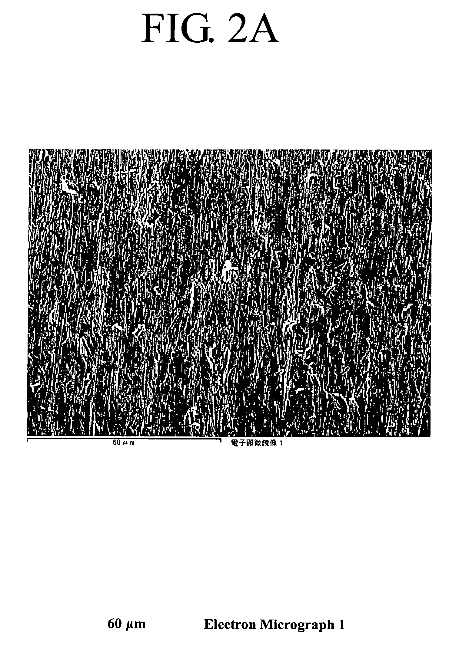
[0106]Next, the results of tests for comparison of workpieces subjected to substrate treatment by the method of the present invention, as well as those after coatings were formed thereon, with workpieces subjected to substrate treatment by a known blasting method, as well as those after coatings were formed thereon, will be shown.

Examination of Embedded Abrasive Grains

[0107]Next, the results of examination of embedded abrasive grains on workpieces formed of various materials and subjected to different substrate treatments, including samples subjected to substrate treatment by the method of the present invention, untreated samples, and samples subjected to substrate treatment by a typical blasting method, will be shown below.

[0108]Cold-Rolled Steel Sheet (SPCC) Treatment Test

[0109]Processing Conditions

example

[0110]The substrate treatment method (Example) of the present invention was performed under the conditions shown in Table 2 below.

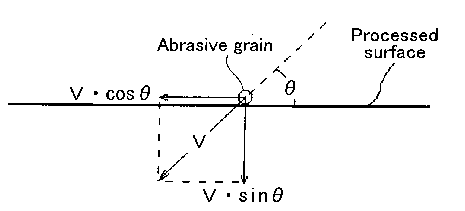
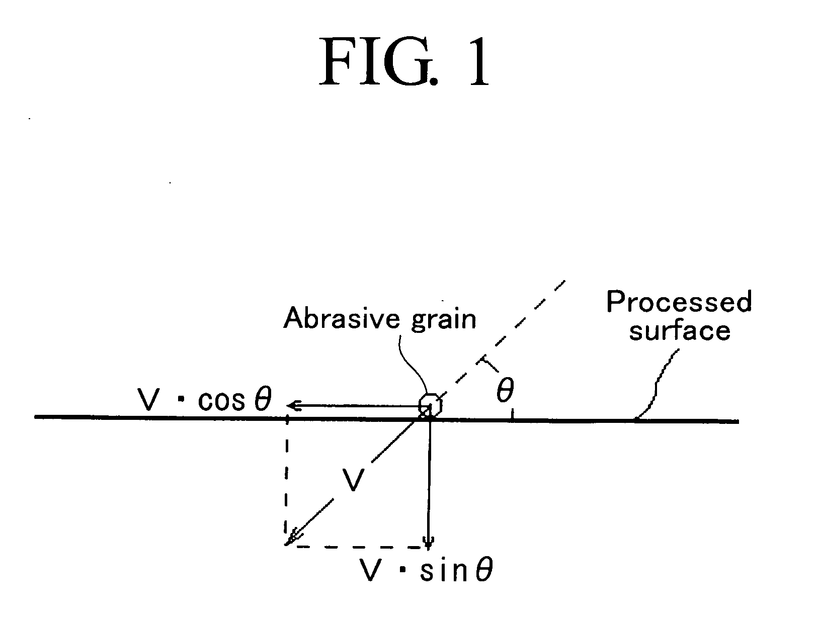
TABLE 2Processing Conditions for Substrate Treatment under the present Invention (Example 1-4)Example 1Example 2Example 3Example 4WorkpieceCold-RolledAlloy Tool SteelCemented CarbideAluminumSteel Sheet(SKD11)(KHO3) manufactured by(A1100)(SPCC)Sumitomo Electric Industries, Ltd.Blasting“FDQ-SR”“SG-SR”“SG-SR”“LDQ-SR”MachineFuji Mfng.Ejection MethodDirect-pressureGravityGravityDirect-pressure (Blower)Compressed airCompressorCompressorCompressorBlowerSupply methodCondition Of EjectionPressure (MPa)   0.3  0.2   0.5   0.02Ejection 705010050distance(mm)Incident angle θ° 3045 6075Nozzle-tip 810 610diameter(mm)Ejection materialAbrasive grains compounded and dispersed in the base materialElastic abrasiveAverage650353501000 grain sizeMinimum (μm)50020200800 Maximum (μm)800505001200 Base materialRubberAbrasive grains“Fujilundum GC”“Fujilundum GC”“Fujilundum WA”“Fujil...


PUM

PropertyMeasurementUnit
average grain sizeaaaaaaaaaa
grain sizeaaaaaaaaaa
incident angleaaaaaaaaaa

Abstract

A portion to be coated of a workpiece is subjected to substrate treatment by blasting to provide an anchor effect without leaving abrasive grains thereon. A substrate treatment method for a portion to be coated includes ejecting an elastic abrasive onto a portion to be coated of a workpiece to form irregularities with a predetermined surface roughness, thereby providing an anchor effect for a coating to be formed without causing the abrasive grains to be embedded in the surface of the workpiece. The elastic abrasive includes elastic carriers and abrasive grains, particularly, insulating abrasive grains, compounded and dispersed in the base material as an elastic body or carried on surfaces of the base materials by, for example, adhesion.

Description

BACKGROUND OF THE INVENTION[0001]1. Field of the Invention[0002]The present invention relates to substrate treatment methods for a portion on which a coating is to be formed (referred to as a “portion to be coated” in the present invention) of an article to be treated, namely, a workpiece, and particularly to a substrate treatment method for a portion to be coated of a workpiece, such as a sliding part, by blasting before a coating is formed on the surface of the sliding part for various purposes, including increased hardness, reduced friction, improved corrosion resistance, improved high-temperature oxidation resistance, and decoration.[0003]2. Description of the Prior Art[0004]The term “blasting” used in the present invention refers to a wide variety of blasting methods by which an abrasive can be ejected onto a portion to be coated of a workpiece at a predetermined ejection speed and pressure. Examples of blasting methods include fluid blasting, such as dry blasting and wet blast...

Claims


Application Information

Patent Timeline
Patent Type & Authority Applications(United States)
IPC IPC(8): B24C1/04B24C11/00
CPCB24C1/06B24C11/00B24C1/08B24C1/10B24C11/005
Inventor MASE, KEIJIISHIBASHI, SHOZO
Owner FUJI MFG CO LTD
Why Eureka
Try Eureka