Implant

a technology of implants and x-ray markers, applied in the field of implants, can solve the problems of laborious and expensive configuration of x-ray markers of this type on implants, and achieve the effects of avoiding rejection reactions, good properties, and being applied particularly easily

Inactive Publication Date: 2008-09-25
AESCULAP AG
View PDF3 Cites 17 Cited by
  • Summary
  • Abstract
  • Description
  • Claims
  • Application Information

AI Technical Summary

Benefits of technology

[0032]To avoid rejection reactions, it is advantageous if the osteointegrative coating is a coating containing titanium.
[0033]However, it is particularly advantageous if the osteointegrative coating is a pure titanium coating. A coating of this type has particularly good properties for the growing on and in of bone into the implant.
[0034]The osteointegrative coating can be applied particularly easily, in particular on implants produced from plastics materials if it is produced by cold gas spraying.
[0035]In addition, it has the same advantages as a marker coating produced by cold gas spraying.
[0036]For a stable, lasting coating which facilitates the growing in of bone, it is advantageous if the osteointegrative coating has a thickness in the range from 0.2 mm to 0.5 mm.
[0037]It is favourable if the osteointegrative coating is thicker than the marker coating. This configuration in particular allows the implant to be coated completely, for example to be provided with a thick osteointegrative coating on the contact faces, and all the other side faces of the implant to be provided with a thinner marker coating. A bone which is grown into the implant could then nevertheless be seen in a radiograph.

Problems solved by technology

The disadvantage in X-ray transparent materials of intervertebral implants or else implants for replacing a vertebral body is that to check a positioning of the implants, additional X-ray markers have to be provided on the implant, which allow a position of the implant after an implantation to be checked, for example, on an X-ray image.
It is laborious and expensive to configure X-ray markers of this type on the implant.

Method used


Image

  • Implant
  • Implant
  • Implant

Examples


Embodiment Construction

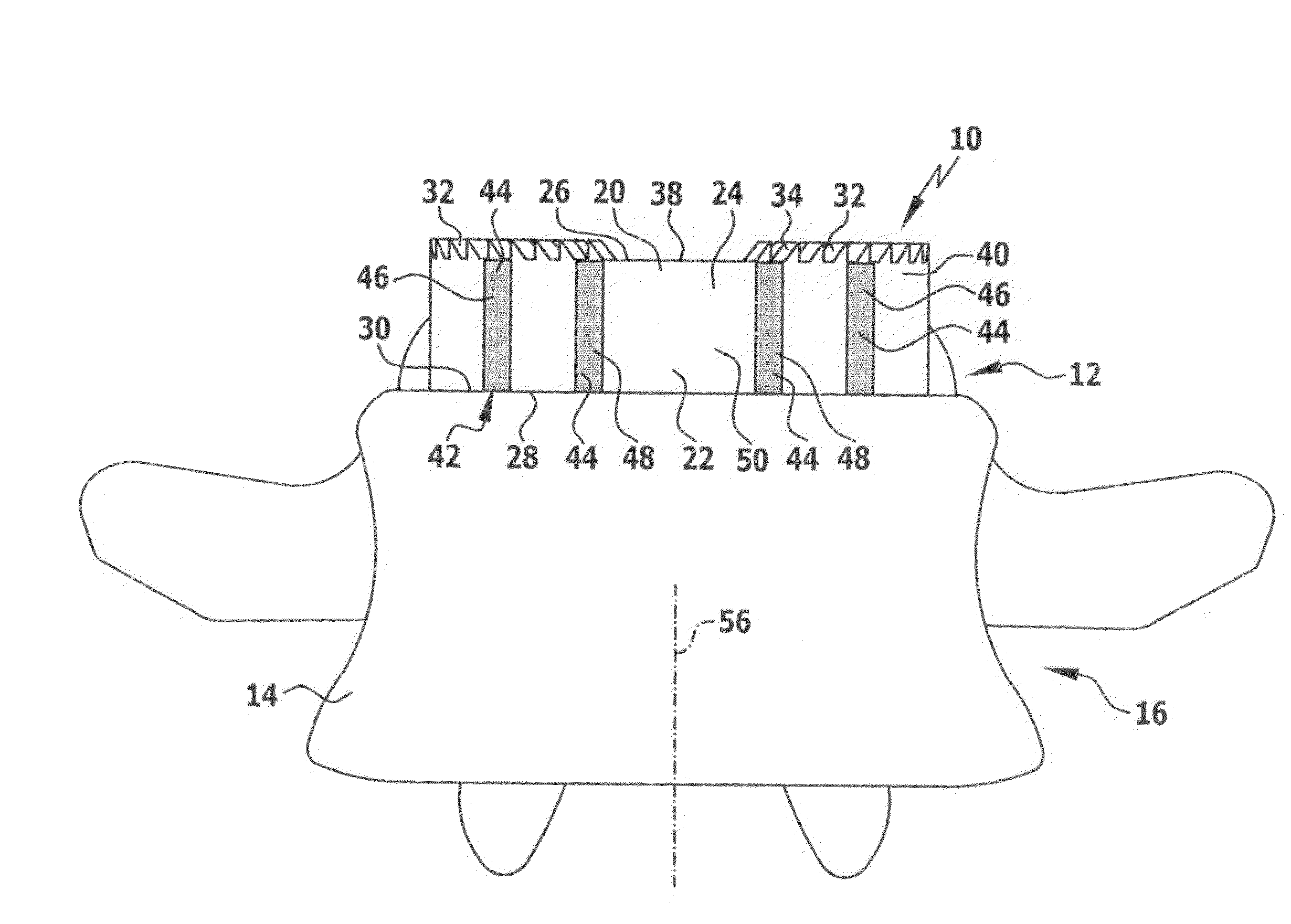
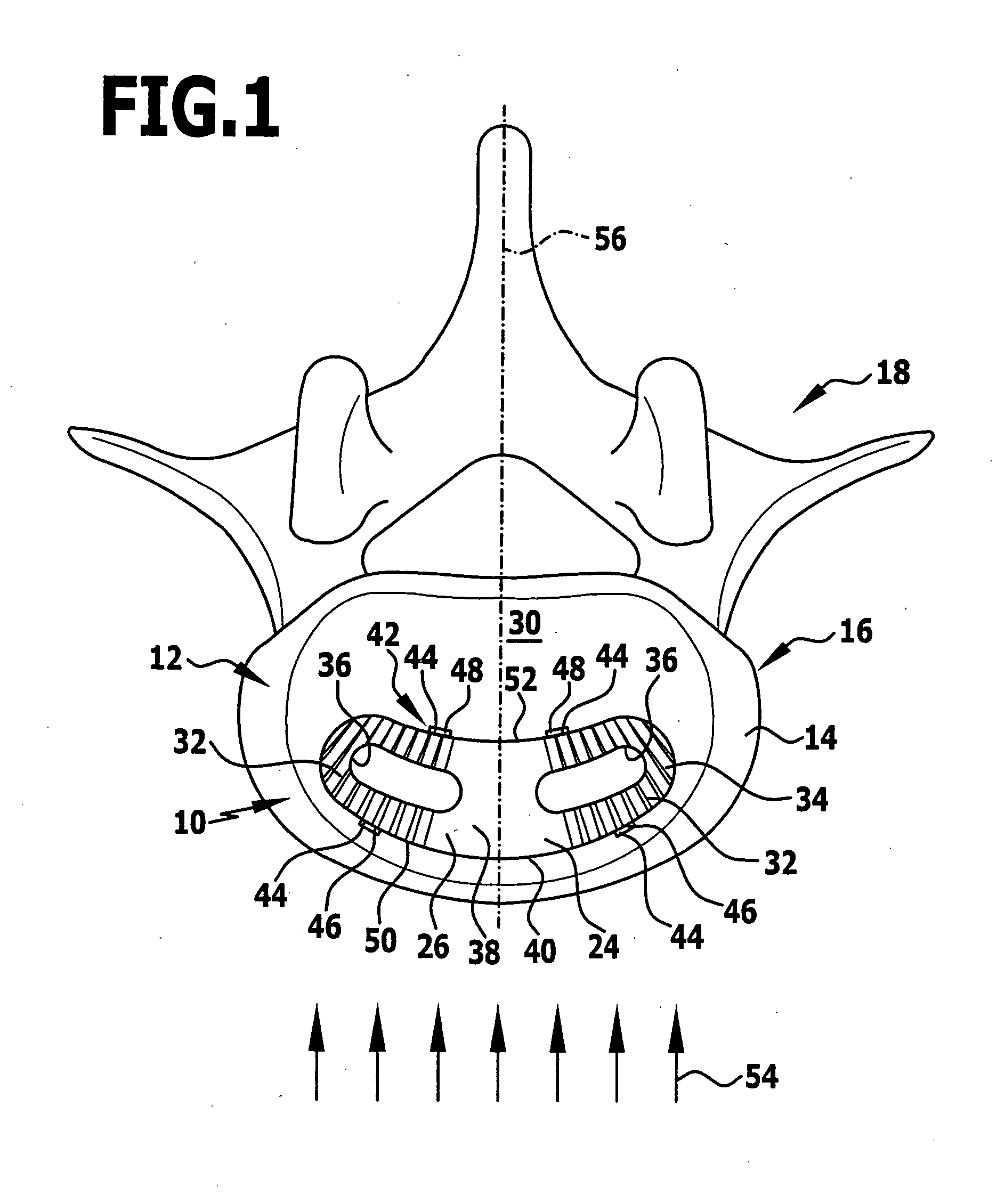
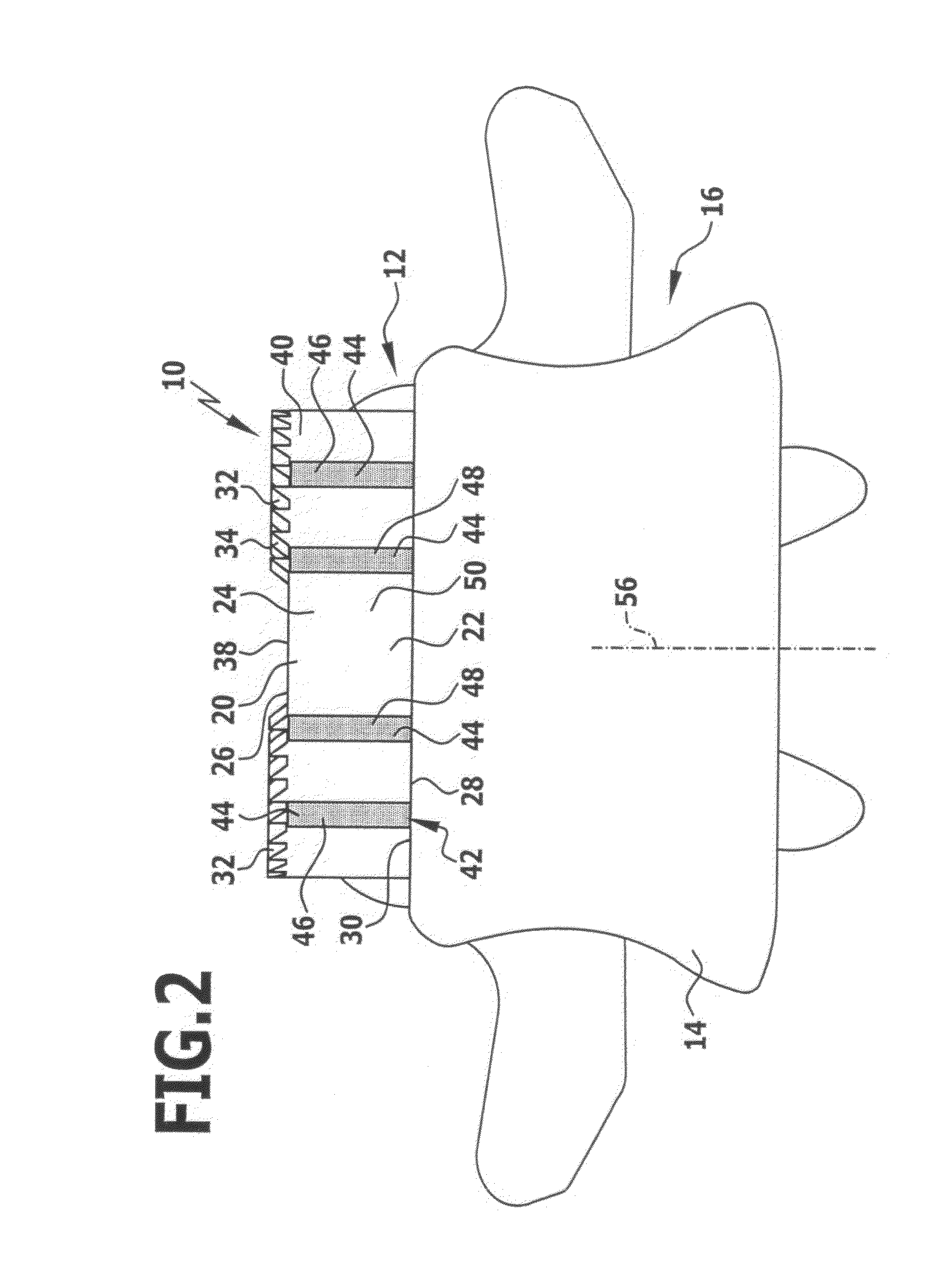
[0041]An implant provided as a whole with the reference numeral 10 is shown by way of example in FIG. 1 for insertion into an intervertebral cavity 12 between adjacent vertebral bodies 14 of two vertebrae 16 of a spinal column 18 of a patient.

[0042]The implant 10 comprises a first contact element 20 and a second contact element 22, which are immovably connected to one another, specifically by a base body 24, which comprises the first and second contact element 20 and 22 and is produced in one piece from the X-ray transparent material. The X-ray transparent material is a plastics material, preferably polyether ether ketone (PEEK). The first contact element 20 comprises a first contact face 26 for resting on a joint face of a first vertebral body 14. The second contact element 22 comprises a second contact face 28 for resting on a joint face 30 of a second vertebral body 14.

[0043]Both the first contact face 26 and the second contact face 28 are structured. In each case, they have two ...


PUM

PropertyMeasurementUnit
angle of inclinationaaaaaaaaaa
particle speedaaaaaaaaaa

Abstract

In order to improve an implant for replacing a vertebral body or for insertion into an intervertebral cavity between adjacent vertebral bodies of a human or animal spinal column, with a first contact face for resting on a joint face of a first vertebral body and with a second contact face for resting on a joint face of a second vertebral body, the implant being at least partially produced from an X-ray transparent material and comprising at least one X-ray marker in such a way that it can be produced more simply, it is proposed that the at least one X-ray marker is configured in the form of an at least partial marker coating, which contains metal as the marker material, of a side face of the implant, which is inclined relative to the first and/or the second contact face by an angle of inclination.

Description

[0001]The present disclosure relates to the subject matter disclosed in German application number 10 2007 014 285. 6 of Mar. 19, 2007, which is incorporated herein by reference in its entirety and for all purposes.BACKGROUND OF THE INVENTION[0002]The present invention relates to an implant for replacing a vertebral body or for insertion into an intervertebral cavity between adjacent vertebral bodies of a human or animal spinal column, with a first contact face for resting on a joint face of a first vertebral body and with a second contact face for resting on a joint face of a second vertebral body, the implant being at least partially produced from an X-ray transparent material and comprising at least one X-ray marker.[0003]In a conventional treatment of a spinal disc incident, a spinal disc arranged between adjacent vertebral bodies in an intervertebral cavity, also called a spinal disc compartment, is completely or partly removed and the spinal column segment comprising the two ad...

Claims


Application Information

Patent Timeline
Patent Type & Authority Applications(United States)
IPC IPC(8): A61F2/44
CPCA61F2/3094A61F2/44A61F2/442A61F2/4425A61F2/4455A61F2310/00407A61F2002/3008A61F2002/3071A61F2002/3092A61F2250/0085A61F2250/0098A61F2/4465
Inventor WAGNER, CECILEZELLER, RICHARDBEGER, JENS
Owner AESCULAP AG
Why Eureka
Try Eureka