Eureka AIR delivers breakthrough ideas for toughest innovation challenges, trusted by R&D personnel around the world.

Test apparatus and electronic device

Inactive Publication Date: 2008-09-25
ADVANTEST CORP
View PDF8 Cites 0 Cited by
  • Summary
  • Abstract
  • Description
  • Claims
  • Application Information

AI Technical Summary

Benefits of technology

[0009]Therefore, one advantage of the present invention is to provide a test apparatus and an electronic device that can solve the above described problems. This advantage is achieved by combining the features recited in independent claims. Then, dependent claims define further effective examples according to the present invention.
[0010]Thus, one aspect of the present invention provides a test apparatus for testing a device under test. The test apparatus includes: a timing data output section for outputting timing data to define at least one of a timing of modifying a test signal provided to the device under test and a timing of acquiring an output signal outputted by the device under test; a variable delay circuit for delaying a reference clock pulse of the test apparatus by a delay amount corresponding to designated delay data so as to generate a timing signal having a transition point corresponding to the at least one timing; and a range modification section for modifying the change amount of the delay data when the timing data are changed by one unit based on the change of a setting range within which the at least one timing is set.
[0011]Here, all necessary features of the present invention are not listed in the summary of the invention. The sub-combinations of the features may become the invention.

Problems solved by technology

If a circuit that has a dynamic range of as many as thirty bits for generating timing signals is to be implemented, the circuit would be too large in size.

Method used


Image

  • Test apparatus and electronic device
  • Test apparatus and electronic device
  • Test apparatus and electronic device

Examples


Embodiment Construction

[0015]The invention will now be described based on preferred embodiments, which are not intended to limit the scope of the invention, but to exemplify the invention. All of the features and the combinations thereof described in the embodiments are not necessarily essential to the invention.

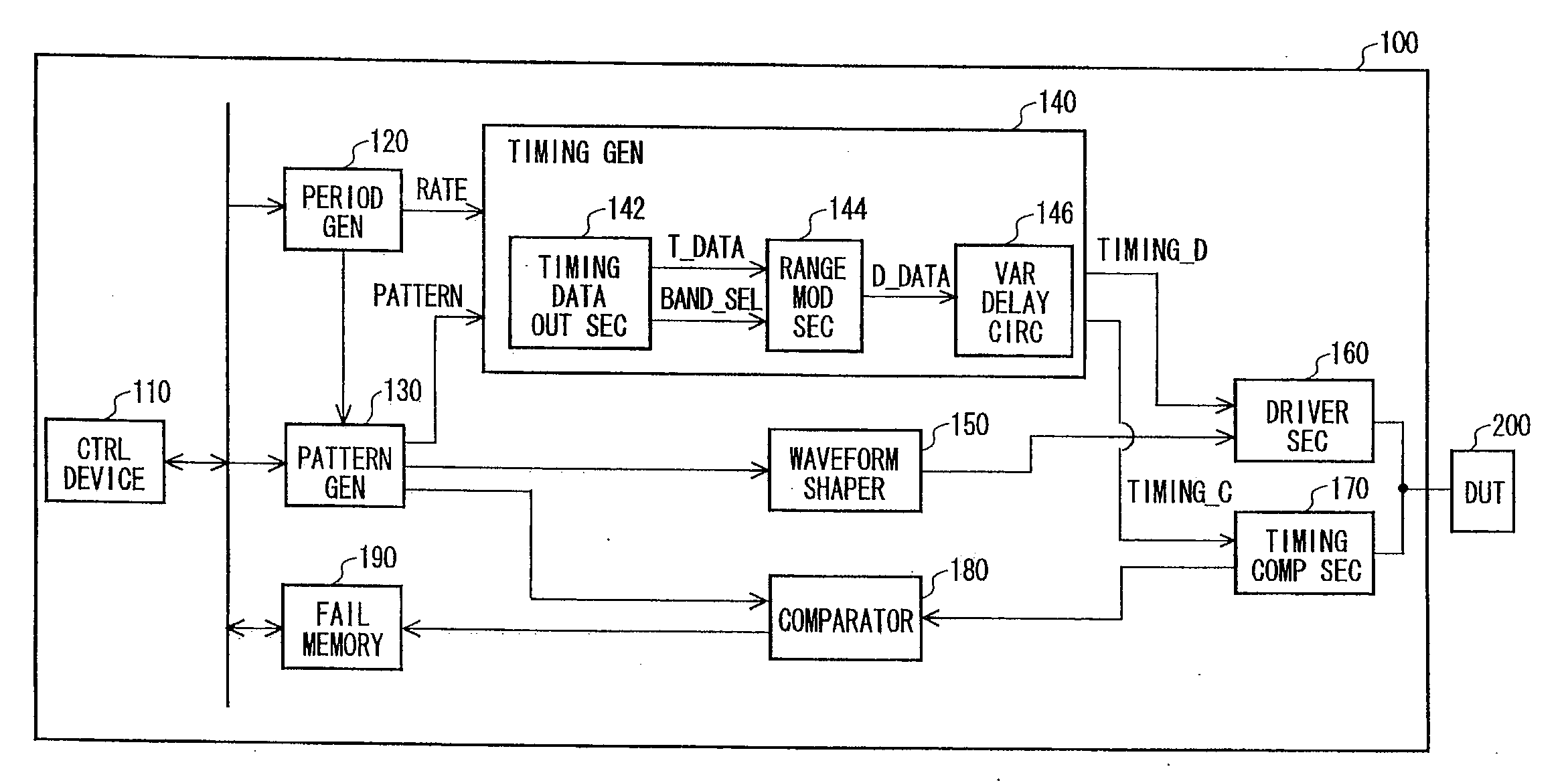
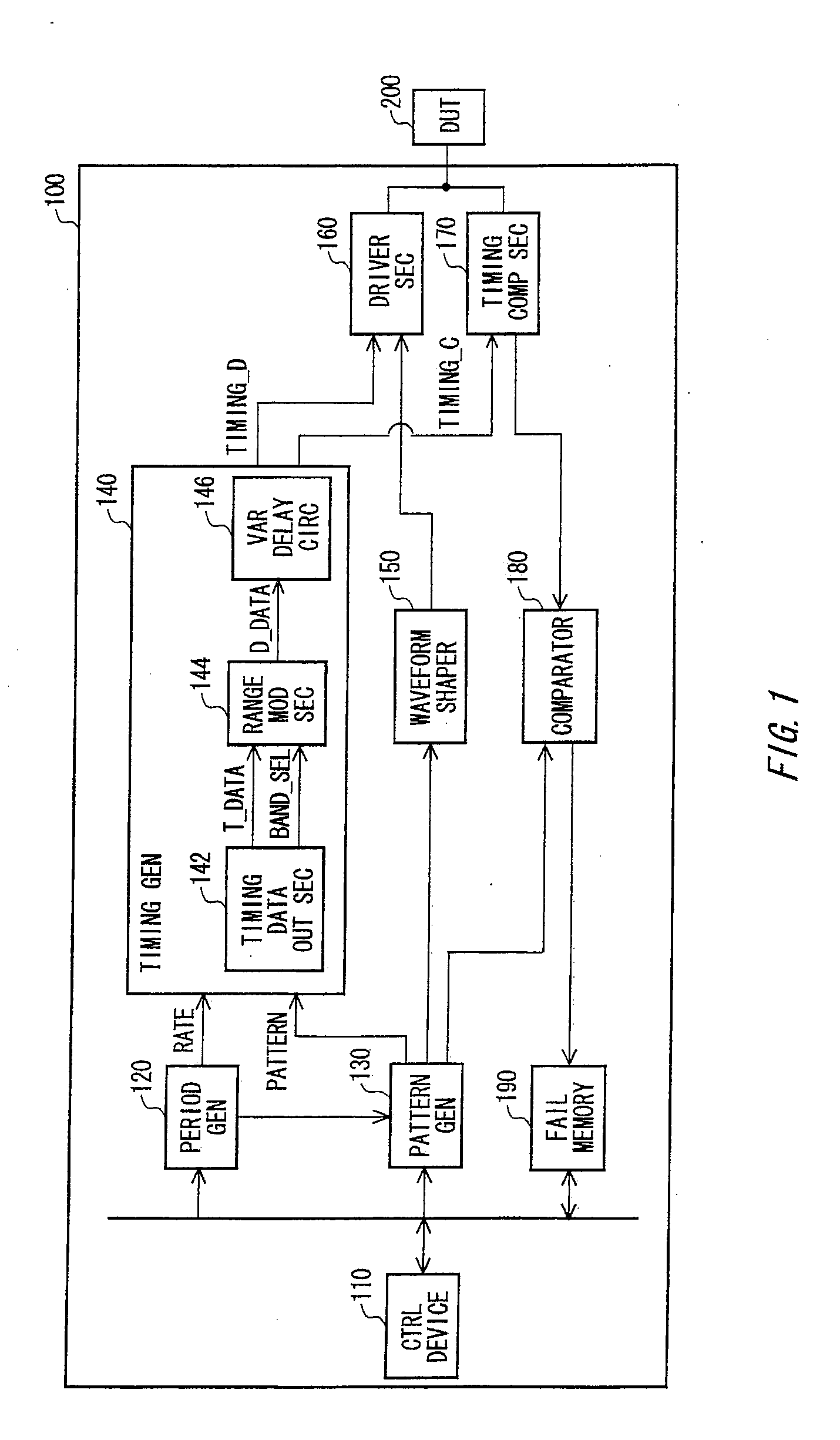
[0016]FIG. 1 shows a configuration of a test apparatus 100 along with a DUT 200 according to one embodiment of the present invention. The test apparatus 100 tests one or more devices under test (DUTs) 200. Examples of the DUT 200 include, but are not limited to, a memory LSI such as a dynamic random access memory (DRAM) or a flash memory, a logic IC, a logic LSI and the like.

[0017]The test apparatus 100 includes a control device 110, a period generator 120, a pattern generator 130, a timing generator 140, waveform shaper 150, a driver section 160, a timing comparing section 170, a comparator 180 and a fail memory 190. The control device 110, which may include a computer system, controls the test f...


PUM


Abstract

A test apparatus for testing a device under test is provided. The test apparatus includes: a timing data output section for outputting timing data to define at least one of a timing of modifying a test signal provided to the device under test and a timing of acquiring an output signal outputted by the device under test; a variable delay circuit for delaying a reference clock pulse of the test apparatus by a delay amount corresponding to designated delay data so as to generate a timing signal having a transition point corresponding to the at least one timing; and a range modification section for modifying the modification amount of the delay data when the timing data are changed by one unit in response to a change of a setting range within which the at least one timing is set.

Description

BACKGROUND[0001]1. Technical Field[0002]The present invention relates to a test apparatus and an electronic device. More specifically, the present invention relates to a test apparatus and an electronic device enabling low-speed and high-speed devices or a device having both low-speed and high-speed sections to be tested with a single test apparatus.[0003]2. Related Art[0004]A test apparatuses for testing a device under test (DUT) receive output signals from the output terminals of the DUT in response to test signals inputted to the input terminals. Then, the test apparatus compares the output signals with an expected value that is expected when the test signals are inputted to the DUT, so that the functions of DUT are tested. Here, the timings for inputting the test signals to each terminal of the DUT are designated by timing signals generated by a timing generator. Also, the timings for acquiring the output signals from the DUT are designated by strobe signals generated by the tim...

Claims


Application Information

Patent Timeline
IPC IPC(8): G06F19/00G01M99/00
CPCG01R31/31937G01R31/31922
Inventor GOISHI, MASARU
Owner ADVANTEST CORP
Why Eureka
Eureka Blog
Learn More