Multi-axis positioning and measuring system and method of using

a multi-axis positioning and measuring system technology, applied in the direction of mechanical measuring arrangements, measuring devices, instruments, etc., can solve the problems of large selection of probes, source of measuring errors, and limitations of the maximum scanning speed that can be achieved in the prior art, so as to reduce vibration and errors and achieve high speed

Active Publication Date: 2008-10-02
HEXAGON TECH CENT GMBH
View PDF11 Cites 66 Cited by
  • Summary
  • Abstract
  • Description
  • Claims
  • Application Information

AI Technical Summary

Benefits of technology

[0013]There is therefore a need for a coordinate measuring system which can acquire a large number of coordinate points on a surface of a workpiece, at high speed, and with reduced vibrations and errors. There is also a need of a measuring probe that is adaptable to complex surfaces.

Problems solved by technology

Coordinate measuring systems of the prior art have limitations in the maximum scanning speed that can be achieved, without sacrificing coordinate precision.
In particular, at high scanning speed, the vibrations generated by masses in rapid oscillatory movement are a source of measuring errors.
Another limitation of the known coordinate measuring systems is the need for a large selection of probes, having different dimension and sizes, in order to measure complex workpieces.
Frequent probe changes slow the measure and reduce the efficiency of the system.
Long and massive probes also increase the measuring error and do not tolerate high scanning speeds.

Method used


Image

  • Multi-axis positioning and measuring system and method of using
  • Multi-axis positioning and measuring system and method of using
  • Multi-axis positioning and measuring system and method of using

Examples


Embodiment Construction

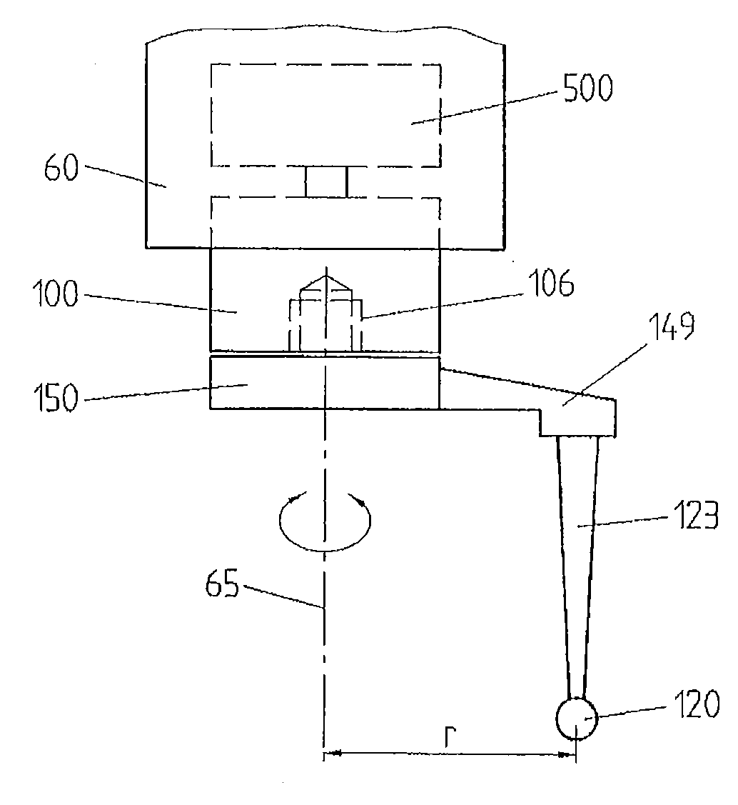
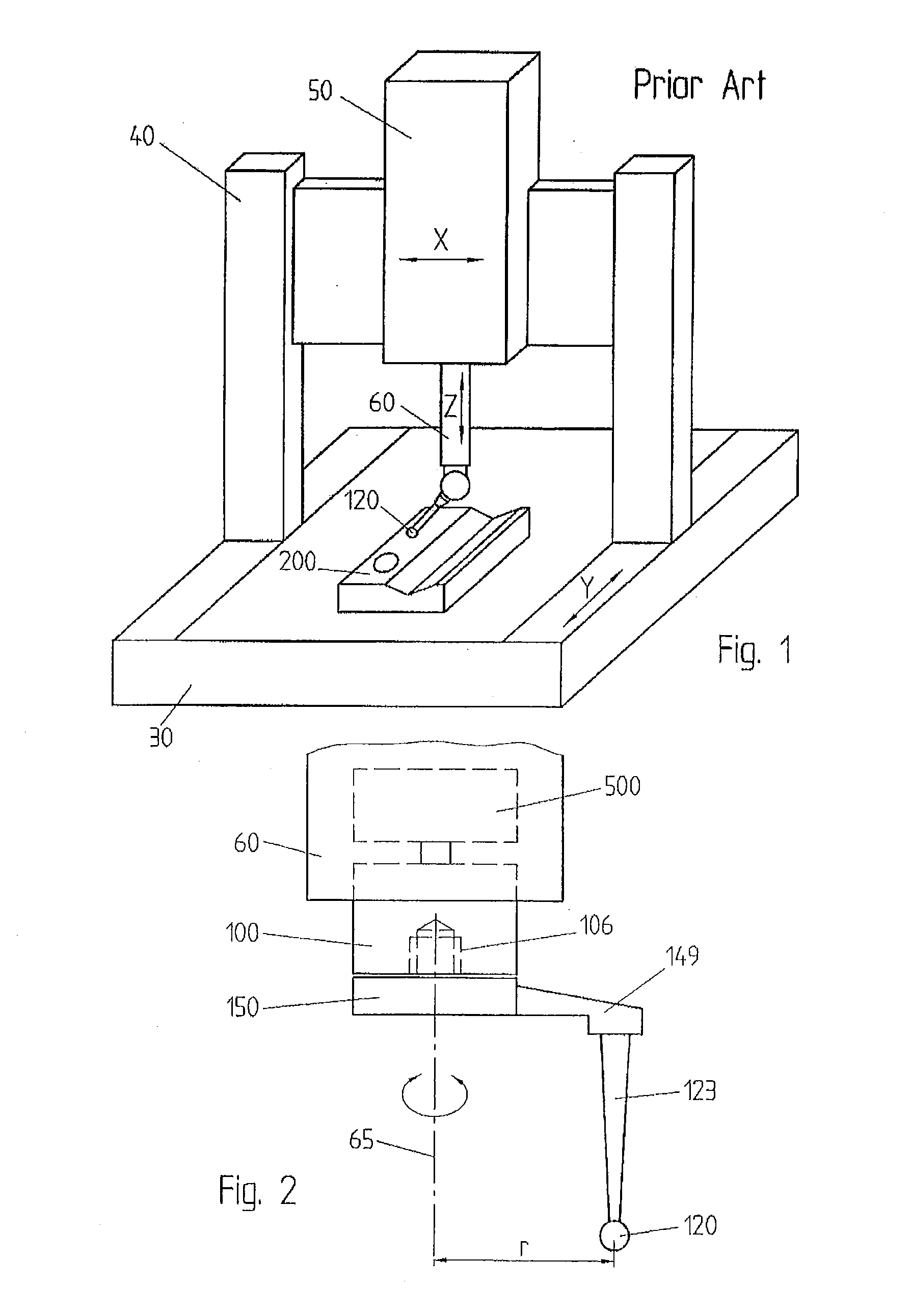
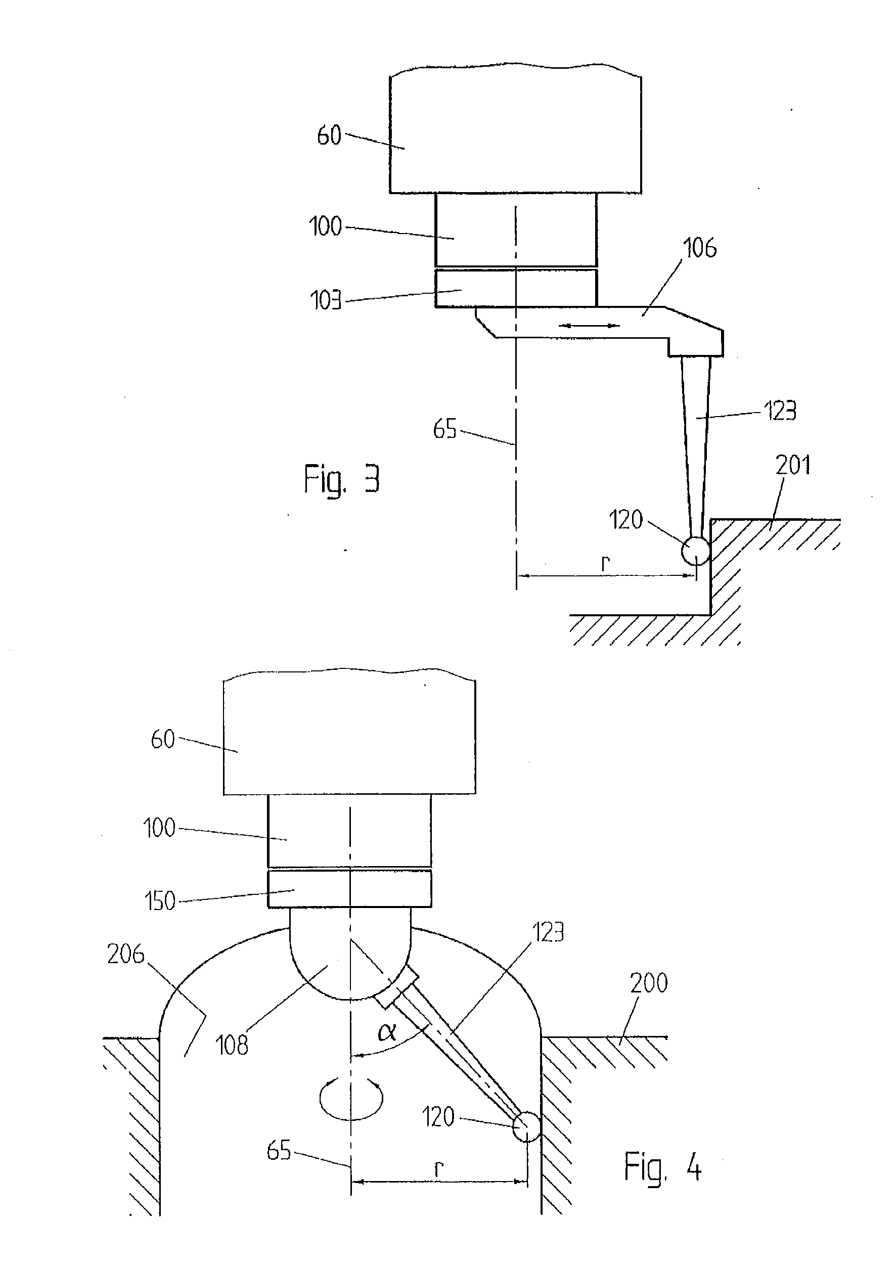
[0023]FIG. 1 shows a contact probe 150 carrying a calibrated ball 120 at the tip of a stylus 123. The contact probe is attached in an offset position to a rotor 100, which is connected to the spindle 60 of the CMM. The rotor 100 can be rotated around the rotation axis 65, parallel to the Z axis of the CMM, by an appropriate actuator, for example an electric motor 500, in the spindle. The angle of rotation of the rotor 100 is encoded by an optical angle transducer, not represented, or by any other appropriate encoder.

[0024]In the following, the direction of the “Z” axis will be designated as the vertical direction, and the plane determined by the “X” and “Y” axes, as the horizontal plane, with reference to the conventional orientation of these axes in a coordinate positioning machine. It must be understood, however, that these conventional direction are used for the sake of simplicity only, and do not limit the scope of the present invention, which can be embodied by measuring machin...


PUM


Abstract

The positioning and measuring system includes a coordinate positioning machine comprising a movable spindle (60) movable relative to a reference surface 30, a rotor (100) rotatably connected with the movable spindle, an actuator (500) for driving the rotor (100) in rotation around a rotation axis (65), and a coordinate probe (150, 190) detachably connectable to the rotor (100) for measuring coordinate of points (350) of a workpiece (200, 201, 250) along a path resulting from the composition of a translation movement of the spindle (60) and a rotation of the rotor (100). The points (350) are offset (r) with respect to the rotation axis (65) of the rotor (100).

Description

REFERENCE DATA[0001]The present patent application claims priority from European application 2007EP-104932, filed on Mar. 23, 2007FIELD OF THE INVENTION[0002]The embodiments of the present invention are broadly concerned with coordinate measure machines and methods of using coordinate measure machines. These are devices for dimensional measuring are used to measure coordinates of points on the surface of mechanical elements, by means of an appropriate measuring probe. The measuring probe that may be of contact type, for example a touch probe, or non-contact type, like an optical probe or a laser probe.DESCRIPTION OF RELATED ART[0003]Coordinate positioning machines, also indicate as coordinate measuring machines, or CMM, generally comprise a fixed reference surface, for example a massive granite table chosen for its high rigidity and dimensional stability, and a kinematics system movable relative to the fixed reference surface and carrying the measuring probe. Examples are known, how...

Claims


Application Information

Patent Timeline
Patent Type & Authority Applications(United States)
IPC IPC(8): G01B5/012
CPCG01B5/008G01B11/03G01B21/04
Inventor JORDIL, PASCALKNUT, SIERCKSPETTERSSON, BOSCHNEIDER, KLAUS
Owner HEXAGON TECH CENT GMBH
Why Eureka
Try Eureka