Fairing for a combustion chamber end wall

Active Publication Date: 2008-10-02
SN DETUDE & DE CONSTR DE MOTEURS DAVIATION S N E C M A
View PDF12 Cites 12 Cited by
  • Summary
  • Abstract
  • Description
  • Claims
  • Application Information

AI Technical Summary

Benefits of technology

[0020]Having a single fastening point per fastener edge avoids problems associated with expansion differences between the assembled-together parts, in the event of such expansion differences being large while the turbomachine is in operation. In addition, since said fastening points are generally provided by means of a fastener element, in particular a bolt, passing through a hole formed in the sector, reducing the number of fastening points as much as possible reduces the

Problems solved by technology

During this step, the bolt needs to be tightened quite considerably in order to take up assembly clearances that are inherent to fabrication and mounting tolerances, and that has the drawback of causing the fairing to lose its annular shape, the inner and/or outer edges of the fairing forming deformation lobes between pairs of bolts, giving these edges a “daisy” shape.
These lobes cause gaps to appear between the assembled parts, giving rise to air leakage and head losses.
In addition, give

Method used


Image

  • Fairing for a combustion chamber end wall
  • Fairing for a combustion chamber end wall
  • Fairing for a combustion chamber end wall

Examples


Example

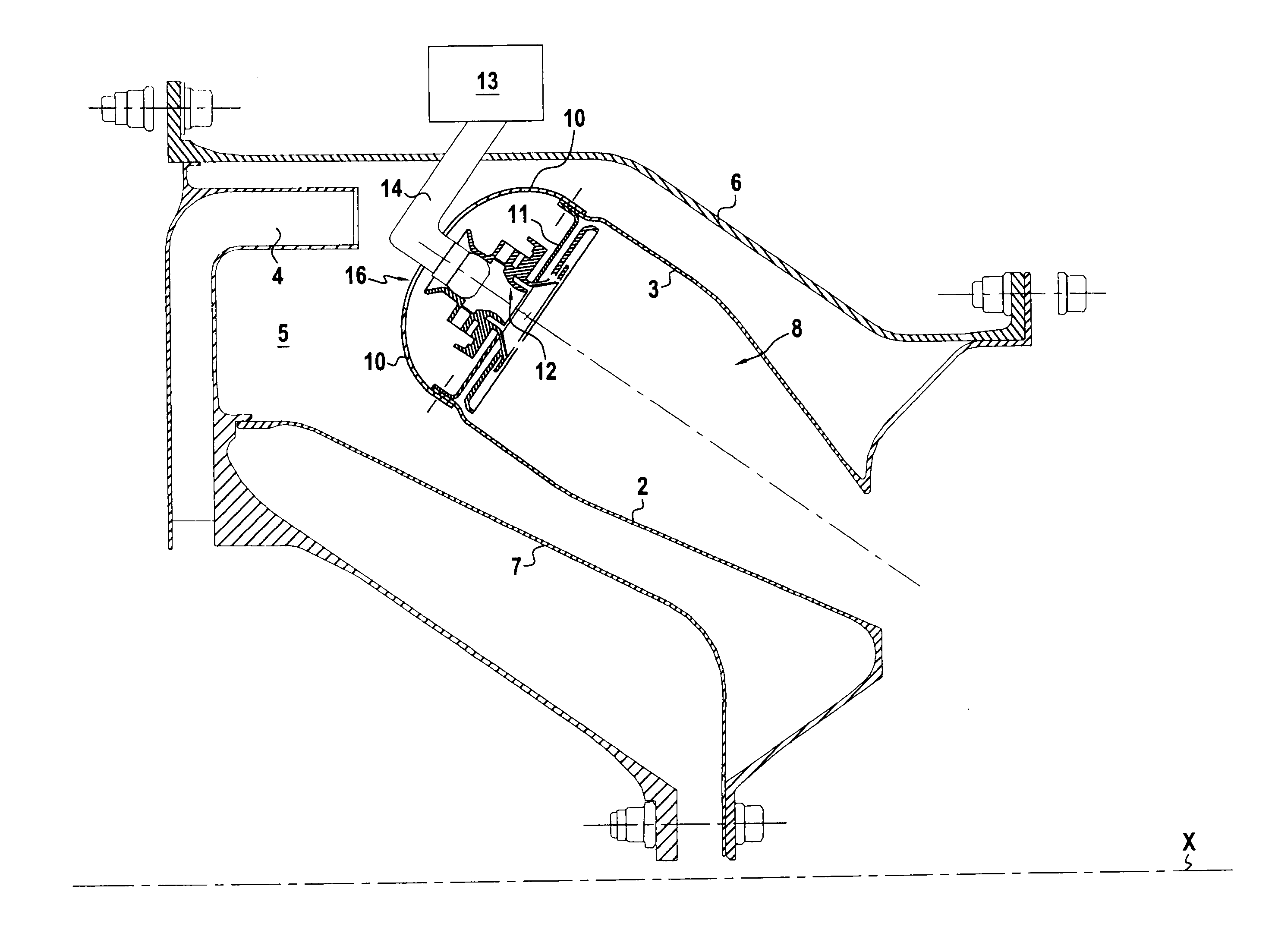
[0028]FIG. 1 shows an example of a turbojet in half-section on a section plane containing the axis of rotation X of the turbojet rotor. The turbojet comprises a centrifugal high-pressure compressor (not shown), and downstream therefrom a diffuser 4 opening out into a space 5 defined between concentric outer and inner casings 6 and 7, and occupied by an annular combustion chamber 8 supported by the casings 6 and 7.

[0029]Although FIG. 1 relates to a turbojet with a centrifugal compressor, the invention is not limited to this type of turbomachine.

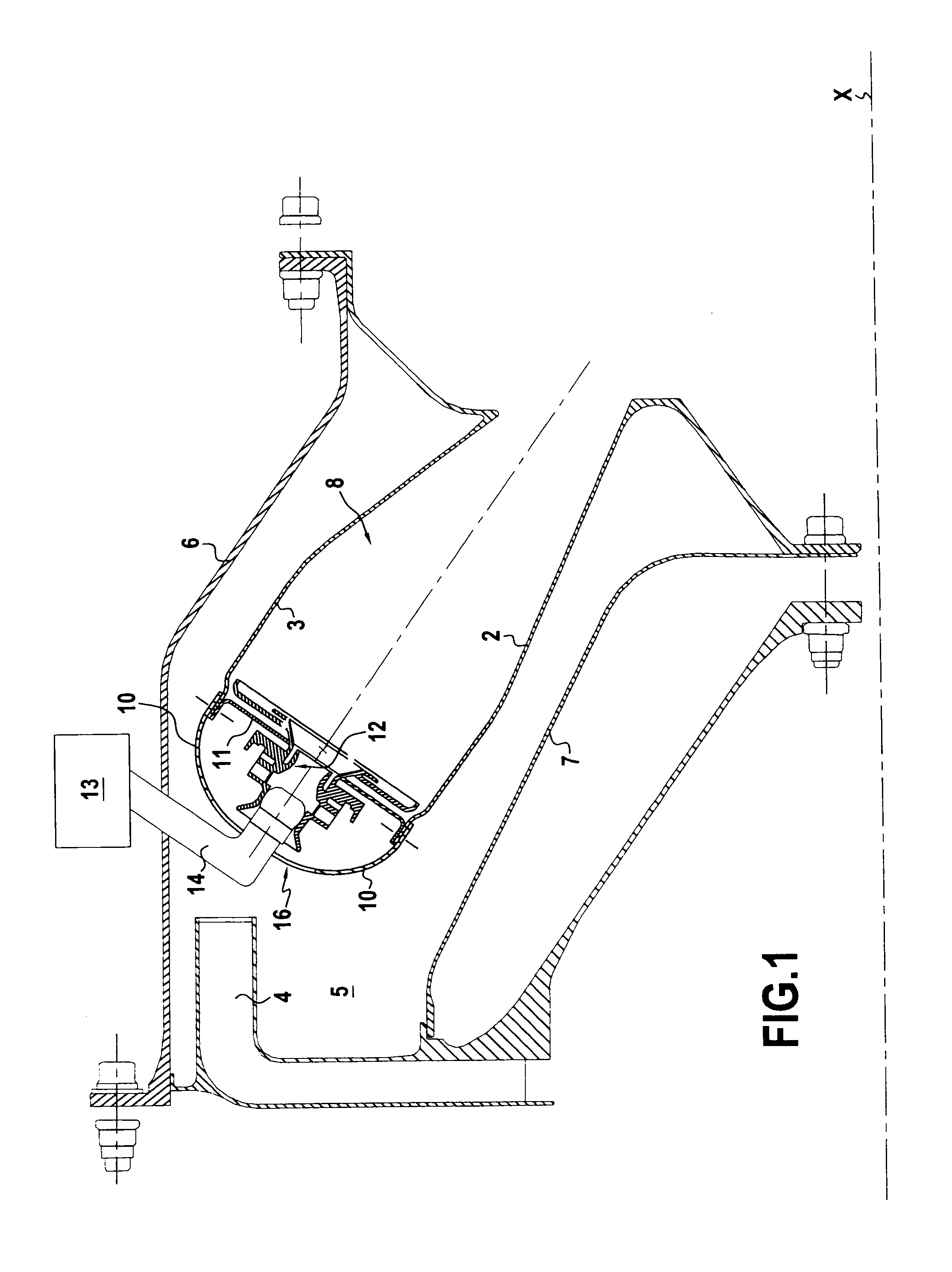
[0030]The combustion chamber 8 has an inner 2 wall, an outer wall 3, and, in the upstream region of said chamber, an annular end wall 11 disposed between said inner and outer walls. This end wall 11 presents inner and outer fastener rims 11a and 11b folded upstream relative to the main portion of the end wall 11.

[0031]The end wall 11 carries injector heads 12 forming part of a system 13 for feeding fuel via fuel injectors 14 passing through th...


PUM


Abstract

An annular fairing for covering the annular chamber end wall of a turbomachine combustion chamber, and in particular of an airplane turbojet. The fairing presents openings for passing fuel injectors that are supported by the chamber end wall. The fairing is subdivided into a plurality of adjacent sectors, each sector presenting inner and outer fastener edges capable of being fastened on either side of said chamber end wall. Each sector includes a lip on one of its side edges, which lip is connected to the remainder of the sector by a step, said lip being designed to over the side edge of the adjacent sector.

Description

[0001]The present invention relates to an annular fairing for covering the annular end wall of a turbomachine combustion chamber. The invention is applicable to any type of terrestrial or aviation turbomachine, and more particularly to airplane turbojets.BACKGROUND OF THE INVENTION[0002]Conventional turbojet combustion chambers comprise an inner wall, an outer wall, and in the upstream region of the chamber, an annular end wall disposed between said inner and outer walls. The chamber end wall supports injector heads that spray fuel into the combustion chamber.[0003]Those conventional combustion chambers also have an annular fairing serving firstly to cover the upstream (i.e. front) end of said chamber end wall together with said injector heads so as to protect them from any impact (as can occur if a bird or a block of ice is ingested into the turbojet), and secondly to ensure that the chamber end wall is aerodynamically contoured allowing air to flow with little head loss.[0004]In t...

Claims


Application Information

Patent Timeline
IPC IPC(8): F02C1/00
CPCF23R3/10F23R3/50F23R3/60
Inventor BUNEL, JACQUES MARCEL ARTHURDE SOUSA, MARIO CESARTOUCHAUD, STEPHANE HENRI GUY
Owner SN DETUDE & DE CONSTR DE MOTEURS DAVIATION S N E C M A
Why Eureka
Try Eureka