Transition-to turbine seal apparatus and transition-to-turbine seal junction of a gas turbine engine

a gas turbine engine and seal junction technology, applied in the field of gas turbine engines, can solve problems such as affecting the design of seals and adjacent components

Active Publication Date: 2008-10-02
SIEMENS ENERGY INC
View PDF7 Cites 27 Cited by
  • Summary
  • Abstract
  • Description
  • Claims
  • Application Information

AI Technical Summary

Problems solved by technology

Maintenance of component temperatures below particular limits is also desired and this may affect design of the seal and adjacent components.
Consequently, the design of such seals has presented a ...

Method used


Image

  • Transition-to turbine seal apparatus and transition-to-turbine seal junction of a gas turbine engine
  • Transition-to turbine seal apparatus and transition-to-turbine seal junction of a gas turbine engine
  • Transition-to turbine seal apparatus and transition-to-turbine seal junction of a gas turbine engine

Examples


Embodiment Construction

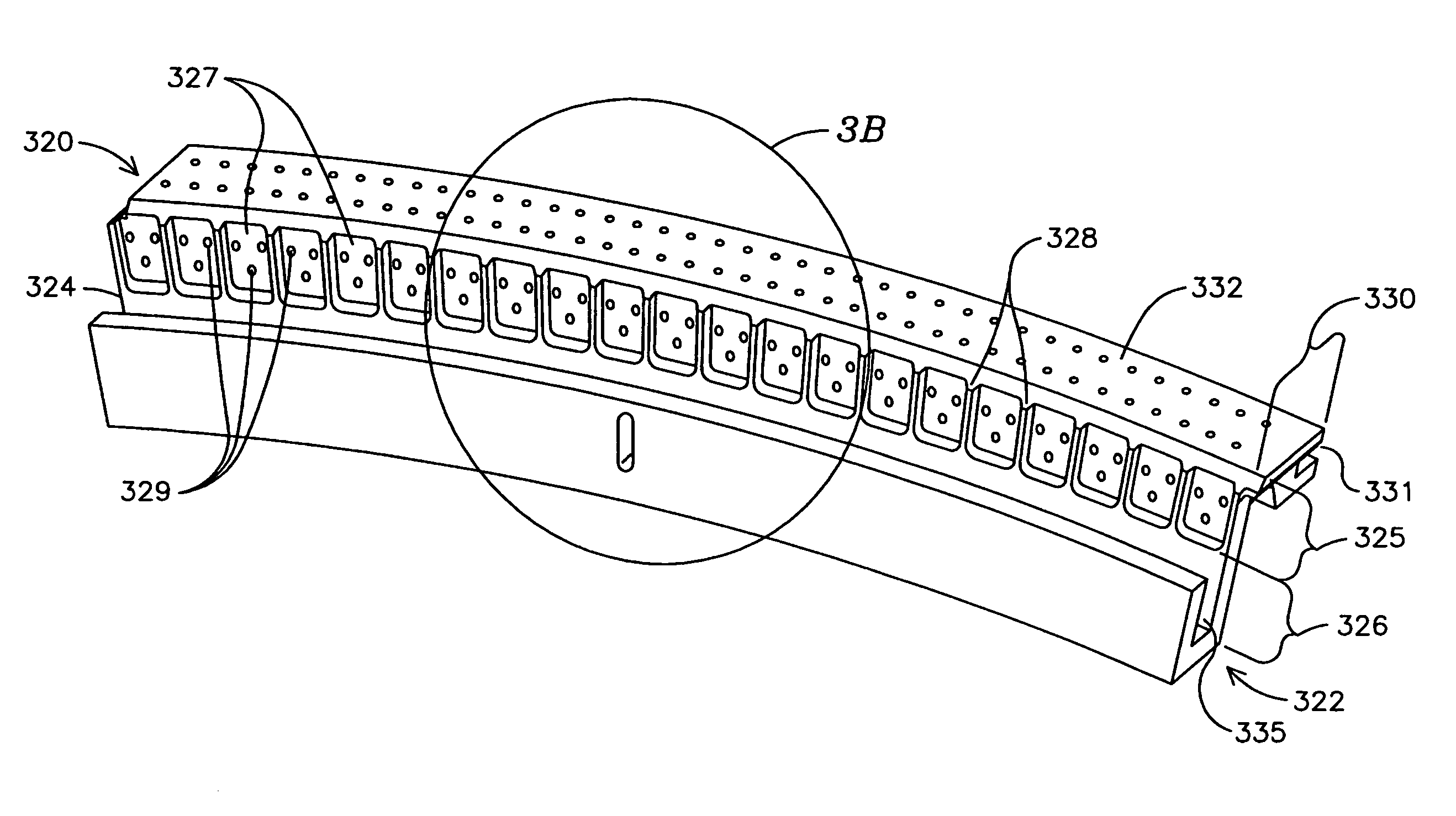
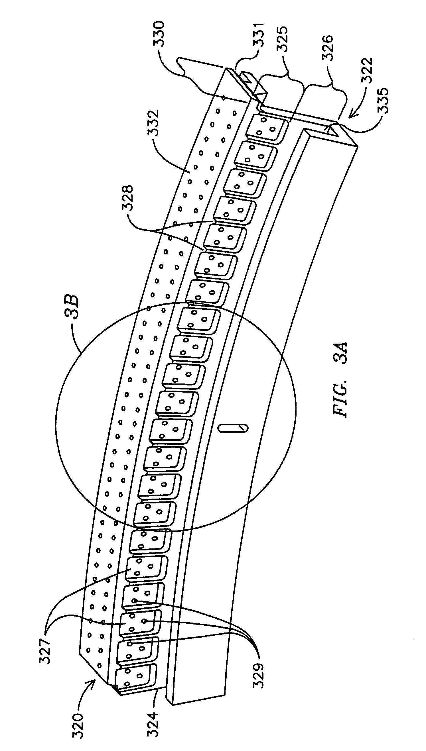
[0011]Embodiments of the invention provide a number of advances over known transition-to-turbine seals, providing enhanced durability by reducing transition metal temperatures and lowering wear rates of adjacent components such as the transition outlet flange. The inventors have developed a transition-to-turbine seal that takes into account pressure impacts of the more downstream row 1 vanes, in particular that a bow wake from the vanes may provide a slight but significant higher pressure region adjacent to an upstream gap between a flange of a transition and the seal. Appreciating that this could result in a circumferential deflection of cooling fluid flows from the seal through the gap, the inventors obviated such possible impacts in embodiments of the present invention, and thereby advanced the art.

[0012]More particularly, embodiments of the present invention comprise a transition-to-turbine seal that comprises a means for keeping a cooling fluid flow in a substantially radial di...


PUM


Abstract

One embodiment of a transition-to-turbine seal (320) comprises an upstream portion (322) adapted to engage a flange (416) of a transition (400). The upstream portion (322) may be U-shaped in cross-sectional profile and comprises a primary wall (324) that comprises a proximal section (325) and a distal section (326) relative to a hot gas path (170). The proximal section (325) comprises a plurality of recesses (327) which are spaced apart and separated by intervening wall (328). In each recess (327) is provided one or more outlets (329) of cooling fluid holes (339). The outlets (329) communicate via the cooling fluid holes (339) with a supply of compressed cooling fluid, such as compressed air that is provided from the compressor. During operation the outlets (329) release this fluid into the respective recesses (327). The flow of cooling fluid through such outlets (329) in the respective recesses (327) provides for a more uniform cooling effect that includes impingement and convective cooling. Further, the outlets and recesses reduce the likelihood of hot gas ingestion due to local pressure gradients. Toward its downstream end, the seal (320) also comprises a downstream groove (321) which is adapted to engage a lip (138, 139) of a row 1 vane segment (130). Variations of the transition-to-turbine seal are described.

Description

FIELD OF INVENTION[0001]The invention generally relates to a gas turbine engine, and more particularly to a seal component between a transition and a turbine of such engine.BACKGROUND OF THE INVENTION[0002]In gas turbine engines, air is compressed at an initial stage, then is heated in combustion chambers, and the hot gas so produced passes to a turbine that, driven by the hot gas, does work which may include rotating the air compressor.[0003]In a typical industrial gas turbine engine a number of combustion chambers combust fuel and hot gas flowing from these combustion chambers is passed via respective transitions (also referred to by some in the field as ducts and tail tubes) to respective entrances of the turbine. More specifically, a plurality of combustion chambers commonly are arranged radially about a longitudinal axis of the gas turbine engine, and likewise radially arranged transitions comprise outlet ends that converge to form an annular inflow of hot gas to the turbine en...

Claims


Application Information

Patent Timeline
IPC IPC(8): F02C7/20
CPCF01D9/023F05D2240/11F05D2240/55
Inventor WEAVER, ADAM J.NORDLUND, RAYMOND S.
Owner SIEMENS ENERGY INC
Why Eureka
Try Eureka