

Injectible two-staged rotary compressor and heat pump system
a rotary compressor and heat pump technology, applied in the direction of heat pumps, positive displacement liquid engines, domestic cooling apparatus, etc., can solve the problems of reducing reliability, and affecting the operation of compressors
- Summary
- Abstract
- Description
- Claims
- Application Information
AI Technical Summary
Benefits of technology
Problems solved by technology
Method used
Image

Examples
first embodiment
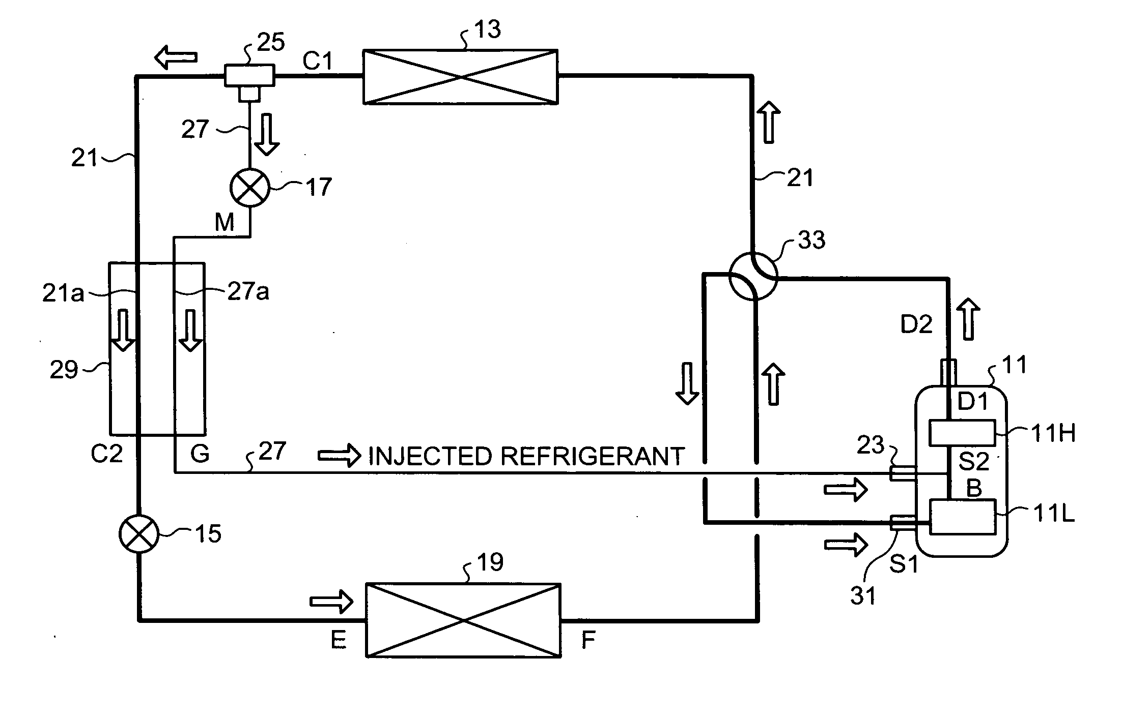
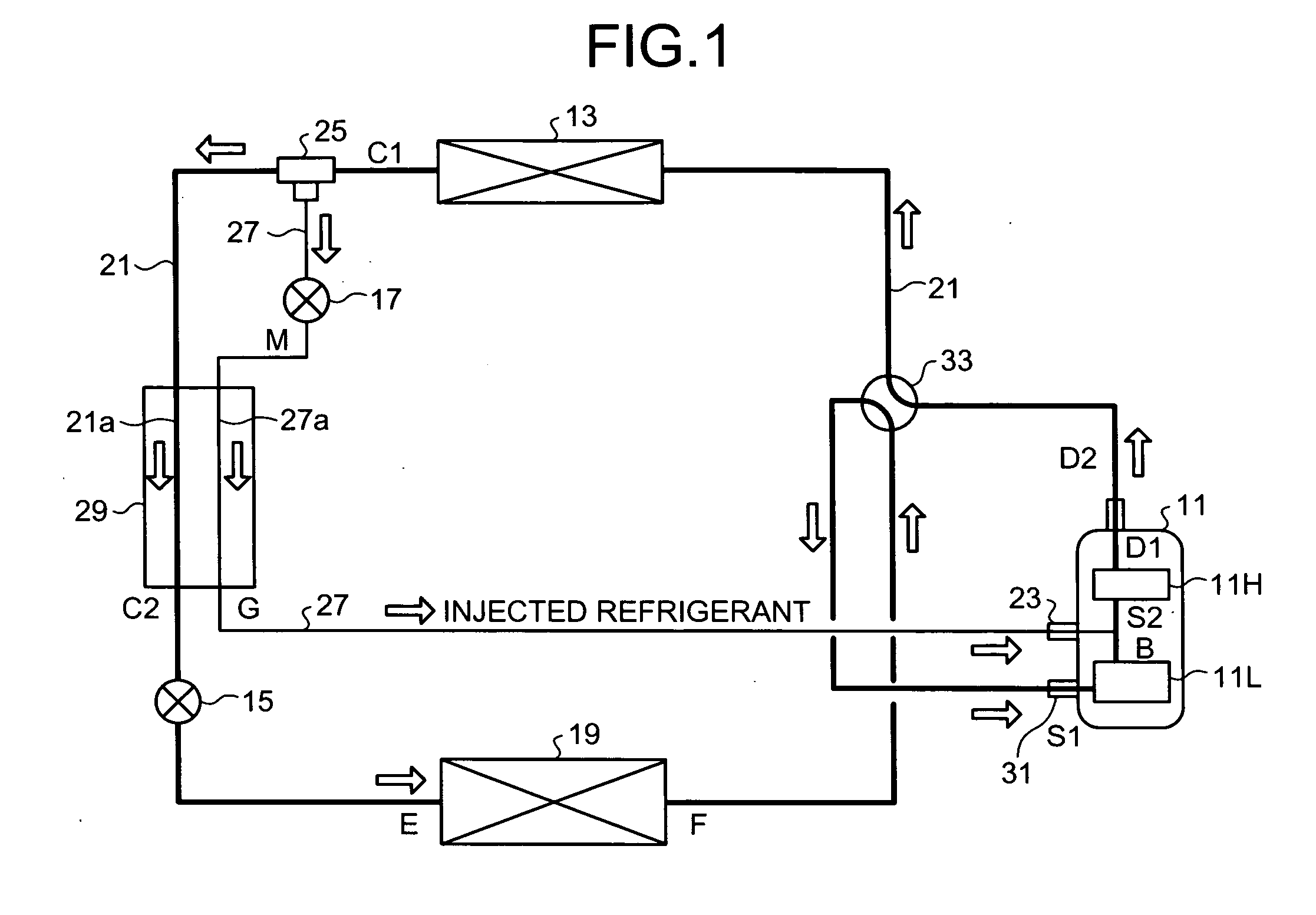
[0037]As shown in FIG. 1, the air conditioner includes an injectable two-staged rotary compressor (hereinafter, “compressor”) 11, a condenser (heat radiator) 13, a first expanding mechanism unit 15, a second expanding mechanism unit 17, an evaporator (heat absorber) 19, and a main circulation pipe 21.
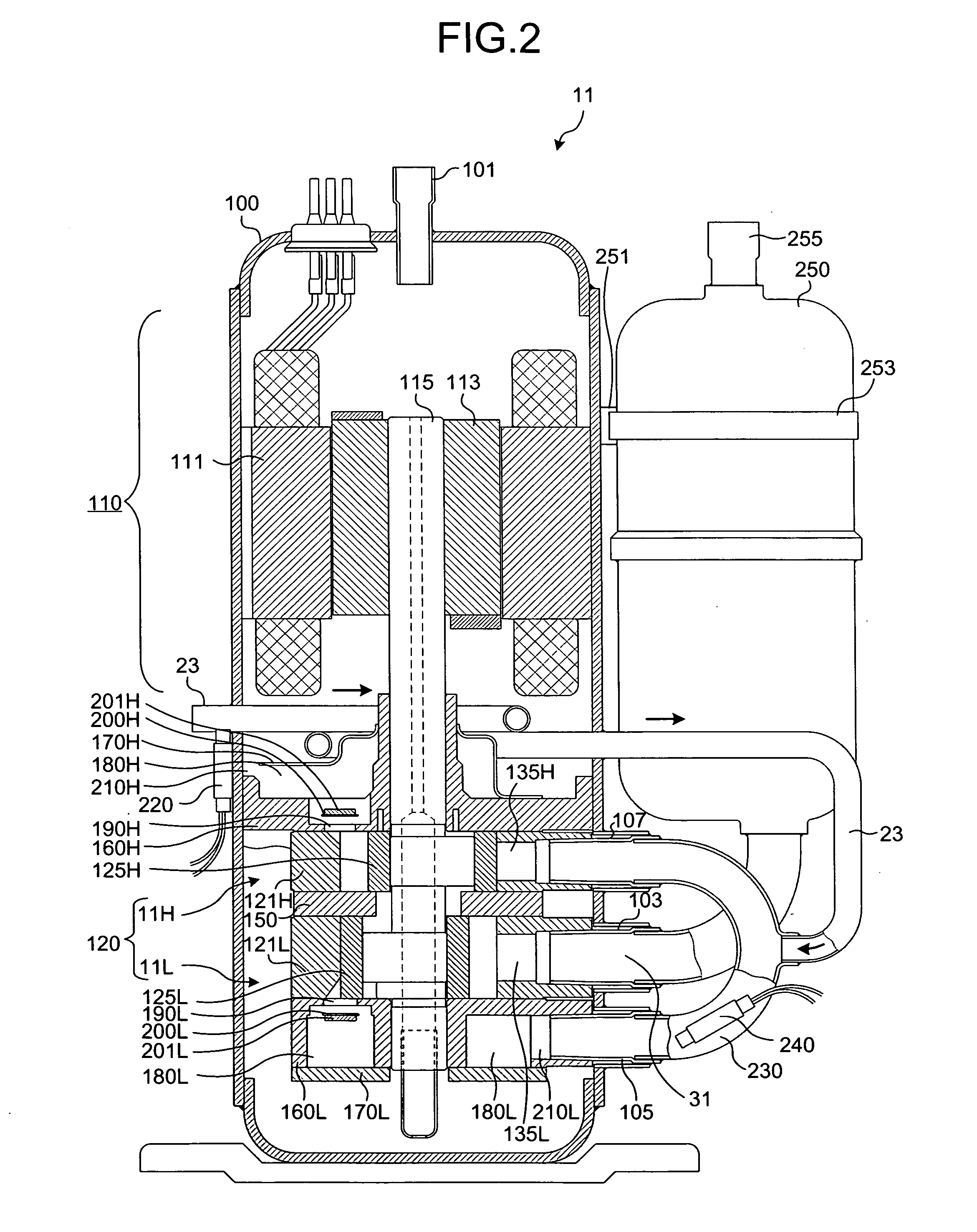
[0038]The compressor 11 is an injectable two-staged rotary compressor, and further includes a lower stage compressing unit 11L and an upper stage compressing unit 11H. The lower stage compressing unit 11L and the upper stage compressing unit 11H are connected by an interconnecting pipe, and a second suction pipe 23 is connected to the interconnecting pipe. The second suction pipe 23 is used to suck an intermediate-pressure injected refrigerant. The intermediate pressure is a pressure between the pressure of the refrigerant in the condenser and the pressure in the evaporator. The compressor 11 is a so-called “inverter compressor”, i.e., the rotation frequency of the compressor 11 can be...
third embodiment
[0109]In the compressor 71 to allow the refrigerant in the compressor 71 to exchange heat, the second suction pipe 23 is extended into the upper stage discharging muffler room 180H in the sealed container 100, and connected to the suction side of the upper stage compressing unit 11H.
[0110]The other elements in the compressor 71 are the same as those according to the first embodiment. Therefore, the same reference numbers as the first embodiment are given in the FIG. 12, and detailed explanations thereof are omitted herein.
[0111]With reference to FIG. 9, it will be now explained how the refrigerant flows through the compressor 71. The basic-cycle refrigerant overheated at the evaporator (heat absorber) 19 flows through the four-way valve 33 and the accumulator 250 to reach the first suction pipe 31. Upon entering the lower stage compressing unit 11L through the first suction pipe 31, the basic-cycle refrigerant is compressed to the intermediate pressure at the lower stage compressin...
fourth embodiment
[0117]In the compressor 81 to allow the refrigerant in the compressor 81 to exchange heat, the second suction pipe 23 is extended into a lubricating oil reservoir 260 located at the bottom of the sealed container 100, and connected to the lower stage discharging muffler room 180L.
[0118]The other elements in the compressor 81 are the same as those according to the first embodiment. Therefore, the same reference numbers as the first embodiment are given in the FIG. 13, and detailed explanations thereof are omitted herein.
[0119]With reference to FIG. 13, it will be now explained how the refrigerant flows through the compressor 81. The basic-cycle refrigerant overheated at the evaporator (heat absorber) 19 flows through the four-way valve 33 and the accumulator 250 to reach the first suction pipe 31. Upon entering the lower stage compressing unit 11L through the first suction pipe 31, the basic-cycle refrigerant is compressed to the intermediate pressure at the lower stage compressing ...
PUM
 Abstract
Description
Claims
Application Information